
Release Highlights 2023T2
Read 2023T2 release highlights and download the latest version in the customer portal.
Outfitting/3D Plant Design
Improved isometric drawings
When creating new isometric groups in Plant Modeller, the automatic splitting into several isometric groups has been improved and the user can easily increase or decrease the number of automatically defined isometric groups by adding or removing a split.
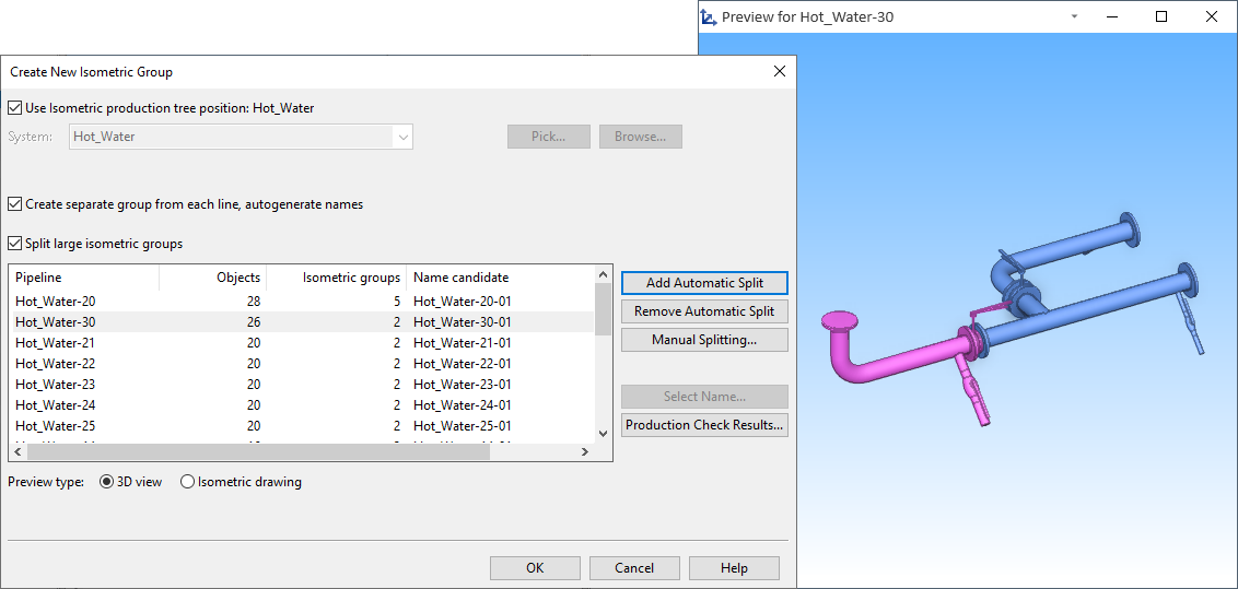
In addition, extra materials (bolts, nuts, washers) can now have parts numbers, and nominal size changes can be indicated with special labels.
Changing the 3D model updates the hole requests
Plant Modeller is now able to automatically update checked-out hole requests if an outfitting designer has, for example, moved the trigger object or changed its nominal size. The new automatic update mechanism can handle penetrations made for pipes, cable trays, air ducts, and equipment (doors, for example). If a hole request cannot be automatically updated or the request is for a multi-pipe penetration, the Plant Modeller user can run a command to update the request.
IFC plate import
Plates imported from IFC format can now be edited in CADMATIC, excluding plates that have holes.
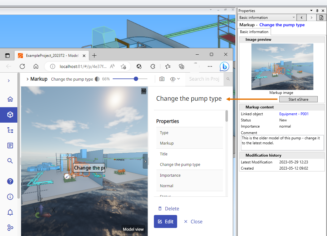
Improved eShare integration
When Plant Modeller is configured to load markups from eShare, the model tree allows the user to locate a markup in the active work view, and area updates notify the users if new markups have been assigned to them. In the markup settings, each user can select whether they want markups to open in eShare App or web browser, and markups also open directly in editing mode.
Improved grid/module line creation
The document editor has a new Grid Lines editor for visualizing the XYZ reference planes of the 3D model in non-axonometric drawing views. Using the editor, one or more grids can be inserted to drawing views on the active page, and the layout and the look of each grid can be customized separately. Reference planes can be shown as lines across the drawing or as "combs" on the sides of the drawing view.
There are several options for displaying the line-to-line dimensions, and the position of each dimension line can be adjusted manually. The visualization of the grids and the dimension lines can be fine-tuned with annotation properties, and since each grid can use a different Annotation Property Defaults configuration, a single drawing view can contain grids that use different line colors, different line widths, and so on.
Figure 1 – Combs
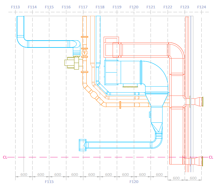
Figure 2 – Grids

Figure 3 – Grid settings
P&ID
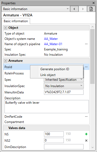
Editable property pane
The new property pane of the P&ID application now allows the user to also edit the data of the selected diagram object, one object at a time. The property pane can be used, for example, to quickly link an object to a different system, pipeline, or specification, to add or remove nominal sizes, to assign a position ID, or to type a value to a data field.
Hull
Hull system
There are several improvements in how the Hull system internally handles project administration. These improvements provide more stability and better performance.
Improved Hull Viewer
Hull Viewer is now powered by a new rendering 3D engine. The new engine allows for larger models, more efficient rendering, and faster model loading. This development is a step towards 3D design in Hull.
Easier to change profiles' material type
It is now possible to change the material type of profiles, pillars, face plates and shell frames at the same time as changing the profile's size or type. Several profiles can be modified in one go.
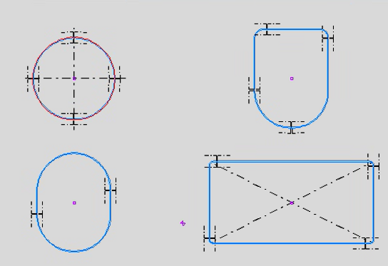
Flexible positioning of face plates in holes
Face plates in standard holes can be set and later adjusted so that they no longer need to start at the middle of the hole contour. This allows for more flexible positioning of face plates in holes.
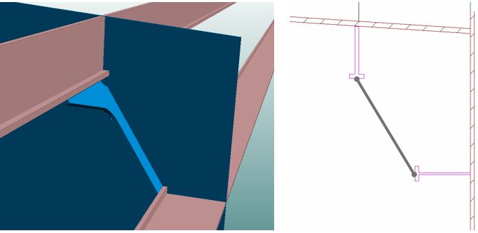
Brackets between parallel profiles
It is possible to create slanted brackets between parallel profiles, face plates and shell frames in plan view and in cross-section. Because such brackets are not part of the plate construction, it is especially quick and easy to create a series of these brackets in cross-section in one go. The brackets have topological connections to their related construction, so they will automatically follow the modifications made to the connected items.
Split shell frames
Several shell frames can be split in one go, just like regular profiles. Previously the splitting had to be done one shell frame at a time.
Automatic marking of watertight plates
It is now possible to make the system automatically mark the desired plates as watertight in cross-section views. Any 2 already defined dash patterns can be used for the markings, and it is also possible to create a dedicated pair of dash patterns for this purpose.
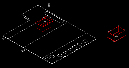
Rotate Work BreakDown sketches
Items in Work BreakDown 3D sketches can be rotated after the selected Work BreakDown branch. This feature is useful when the construction is turned in the workshop at a certain point during assembly. The sketch can be created so that the items on it are rotated in the same way as the part is turned in the workshop.
Exact block definitions when importing NAPA model
The import now uses the exact block definitions of the NAPA model instead of a bounding box that sets the import limits. This allows for correctly importing blocks with slanted block definitions.
Information Management
Submodels in eShare
Submodels are now available also in eShare, to enable for more efficient workflow and allow even more possibilities in shared projects.
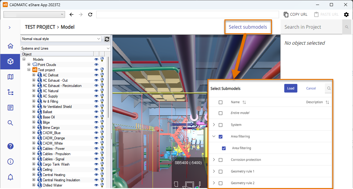
eShare models can be split into submodels with different types of configurations, based on attributes, filtering rules, geometry, or a combination of these. All of the submodels configured in the project are published during the model publish, which makes opening the submodels fast and smooth. This feature makes it easier to handle smaller parts of the project, without having to load the full model every time.
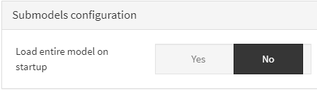
Project administrator can also configure that the full model is not loaded at startup, but submodels are used instead.
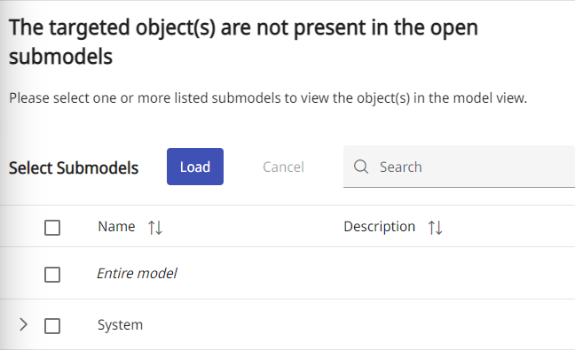
If there is a link in the model to an object that is not present in any of the loaded submodels, eShare offers to load submodels containing the object.
Improved search in eGo
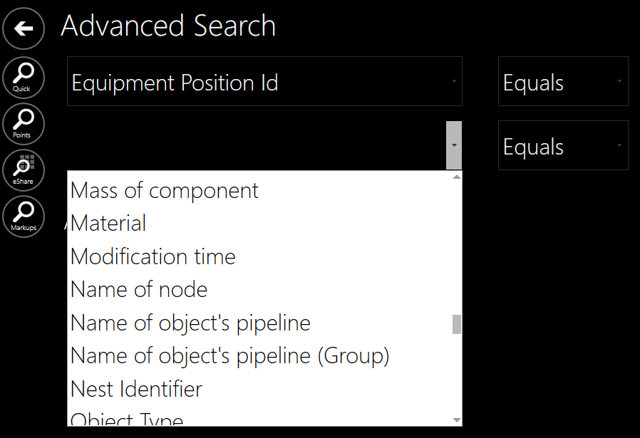
Search in eGo has been improved with a number of new search features for more accuracy and ease of use.
eGo has now quick search for finding just what you need in matter of seconds.

For more search options, there is also advanced search. There are options for searching for markups, Smart Points in eGo, as well as from documents in eShare. Advanced search also enables creating queries with multiple attributes.
Electrical
In CADMATIC Electrical 2023T2, we have continued with the features published previously. The user interfaces and thus the usability have been improved, while the distribution board and group renewal have not been forgotten either.
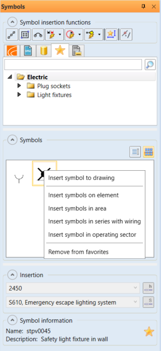
Symbol selection and terminal blocks
In the symbol selection tool, you can now list your favorite symbols on a separate tab. In addition, symbols can be read from a closed drawing file – the drawing file allowing all employees access to the same symbols can be located on the company's network drive, for example. We currently recommend using Electrical symbols only.
Showing symbol occurrences from a drawing – function previously familiar from product models – now also works with individual symbols. You can therefore effortlessly see the desired symbols in the active drawing.
The symbol selection tool now includes terminal blocks, in their own Terminals directory. Inserting a terminal block opens the terminal block insertion function, which has also been improved: you can select the desired terminal block, or create your own and then use it via the insertion function.
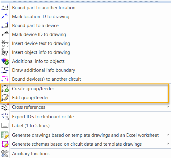
Distribution board and group functions
Distribution board and group functions are an integral part of electrical design; they enable efficient system design and management. The latest improvement in circuit diagrams is the possibility of creating groups of protective devices under certain conditions. The group number is conveniently defined after inserting the device, which allows clear and unique identification.
Previously, only the distribution board’s outgoing feeders were shown in Distribution board and group management, but now the incoming feeders are also available. The incoming feeder data shows the short-circuit current of the feeder, which reduces the need to navigate in the dialog. You can, for example, view the short-circuit currents between the incoming feeder and the outgoing feeders.
The much-desired feature of adding distribution board or group information to a drawing has now been implemented. You can add, for example, the short-circuit current from the incoming feeder defined for a distribution board.
Via the Distribution Boards and Groups tree, you can create the feeding hierarchy for distribution boards, even if there are no occurrences in the drawing. The user can define the hierarchy easily by selecting the supplying distribution board as well as the distribution board supplied by it.
Creating groups has also been made easier by adding a function to import groups and feeders from an Excel file. For example, when it is known in advance that there will be a number of devices, you can define a separate group and feeder for each device in Excel, and then import the data into the database.
Wiring functions
In Schematics, the wiring functions have been refined, continuing the renewal started in earlier releases. For example, showing the From and To information has been improved.
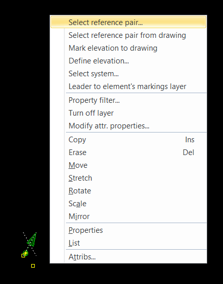
In Layout, you can now make wiring references using rise symbols. Previously, it was only possible to create a wiring reference using the wiring function, but now you can assign a reference pair to a single rise symbol after insertion, similarly to the wiring reference function in Schematics.
Storeys and buildings
The order of buildings has been corrected. In addition, there is a new function that organizes buildings by numbering or alphabetically while maintaining the order based on elevation. This feature is especially useful for projects that include multiple buildings.
Product information
Product information management for cable types has been improved. Product information is now saved in the project along with the cable type. For example, the cable type can be assigned the necessary terminals and other accessories, eliminating the need to define them cable by cable. There are also separate report templates for this information, so that the data can be conveniently listed as a project document.
DB Tool
Auxiliary grids have been added to the Devices tab, allowing you to easily drag pieces of device information into the correct columns in the main grid. Auxiliary grids have previously been used for I/O channels, for example.
Auxiliary grids have also been added to the Cables tab. For example, cables created in the database can thus easily be assigned the From and To information.
In addition, a new tab for I/O channels has been added. This makes it easier to understand the whole I/O environment when I/Os can be viewed at the desired level (I/O, I/O channels, I/O cards).
CADMATIC Electrical Lite
Settings file management features have been added. It is not possible to create new configuration files, but you can select which file to use.