Standalone Intelligent General Arrangement Tool for Holistic Basic Design
Posted on June 22, 2022
This paper was presented for the first time at the annual Conference on Computer Applications and Information Technology in the Maritime Industries (COMPIT) held in Pontignano, Italy from 21-23 June 2022.
Author: Madalina Florean; Verónica Alonso de los Ríos; Juan Prieto; Ludmila Seppälä
The paper describes a standalone intelligent and adaptive General Arrangement tool for holistic improvement of the basic design process in shipbuilding. The approach generates high topology 3D hull structure layouts based on 2D sketches. Furthermore, it uses an open standard format to interact with scantling tools that facilitates the hull definition process and approval. The tool connects hull shape optimization tools, hull design, and outfitting layout, leading to the overall optimized design of vessels. The key features of this new approach are 1) the option to define different design alternatives, specifically in the hull structure, allowing more flexibility in the designing process, 2) the feasibility to manage changes in a more straightforward manner, and 3) the interoperability to exchange data in standard formats to analyze the impact on other aspects of the basic design.
1. Introduction
The basic design stage is a relatively fast process but an essential part of the ship’s lifecycle. It is not straightforward to measure the downstream impact of the quality of basic design. Errors in the detail engineering stage, costly changes in production, lack of efficiency, predictability, and profitability in operation are all aspects that are not easy to consider when an experienced naval architect defines the configuration of a new ship. These aspects have an immediate impact on the ship cost, performance, weight, stability, safety, and manufacturability. The challenge is how design authorities, regulatory bodies, shipyards, engineering companies, and suppliers can improve the simultaneous set of tasks and manage data in diverse software applications.
This paper describes an approach for a standalone software solution that generates the basic design documentation for any type of vessel in a multi-company and multi-software environment. The presumed situation reflects real-life cooperation between naval design and engineering companies, shipyards, shipowners, and regulatory bodies such as classification societies. Often, each participant uses different tools and software solutions focused on specific tasks and presents output documentation in an agreed format. This results in an enhanced need for an overall project follow-up process and impacts the overall shipbuilding management process, Bruce (2021).
Critical aspects covered in this paper include the flexibility to define different design alternatives, specifically in the hull structure and in the main equipment layout configuration, the feasibility to manage simultaneous changes, and the interoperability to exchange data to analyze the impact on other design phases, while ensuring that the requirements and rules and regulations are met.
The general arrangement is the central document for the initial and basic design stages. It is critical to consider requirements for the ship performance specification, hull shape and deck arrangement, definition of fire zones, the layout of the main equipment and the preliminary arrangement of large piping, HVAC, and electrical connections, as well as accommodation areas. A typical general arrangement from a previous similar project is often used. This way, it is possible to get a head start and use it as a basis for further modification and adjustments.
The paper presents a solution that considers the importance of general arrangement preparation and a realistic scenario of fragmented stakeholders and software tools involved in different stages. In the suggested approach for the definition of general arrangements, an entire system of parameters that influences the main dimensions of the vessel can be defined and modified in the whole project, even with external software. As a result, modifying any parameter changes every key construction in the ship and automatically adjusts the stiffening.
The weight estimation and repositioning of the heavy machinery are improved based on the mainframe distribution while all the conditions are automatically considered. The interaction with other scantling tools using a standard format improves a process that usually involves many changes. Finally, the basic design definition can be optimized by connecting the general arrangement tool with optimization tools that ensure the automatic iteration of hull structure parametric values.
All participants benefit in the short term and during the project life cycle via a project that is engineered better with a more holistic view.
2. Adaptive general arrangement
Traditionally ship design has been done according to Evans’ design spiral, Evans (1959). Processes do not always follow theory; there are many interdependencies, some stages start already while previous stages are still ongoing, and changes occur all the time. How can we be agile and adapt accordingly to shipbuilding design?
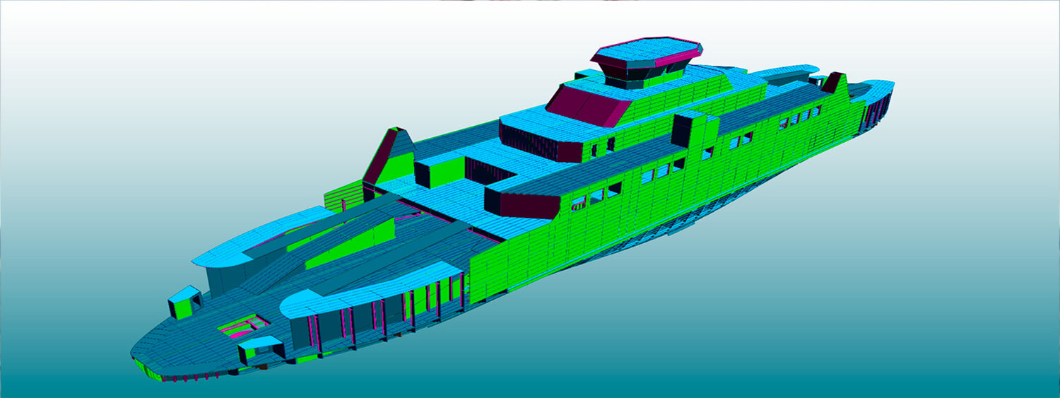
The General Arrangement preparation tool must be enhanced with functionality that ensures the fast definition of different ship design alternatives based on a high level of topology, parameters, and reference planes. The solution proposed in this article is innovative as it allows the definition of the layout in 3D, based on 2D sketches, with automatic stiffener positioning and pillar definition.
The proposed tool is currently implemented as a part of CADMATIC software applications. It can be linked with other external tools for scantling calculations via a standard format in a bidirectional way. Also, it is possible to connect it with optimization tools for design optimization based on parametric hull values to achieve a more qualified design in less time.
2.1. High level of topology in hull design
Ideally, the 3D model of a vessel is defined so that any changes to the main dimensions or any item in the model at any time triggers the system to update the whole model accordingly. This relieves specialists of the burden of manually changing and checking the model.
During the basic design stage, several dimensions influence the main dimensions of the vessel. They affect, for instance, the ship weight, stability, and damage characteristics. The ability to modify these dimensions at any time throughout the entire project ensures a high level of model malleability. Furthermore, automatic model recalculation gives the naval architect the workspace necessary to optimize the model iteratively.
A high level of topology must be provided to assist the naval architect in the creative process to ensure that the whole model is updated accordingly whenever the main dimensions change. This allows changes to be considered at any stage of the initial design. The required iterations involving assessment from different stakeholders and transformations are triggered by significant equipment adjustments by suppliers or similar parties.
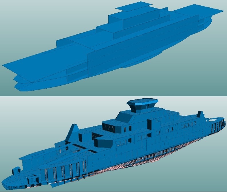
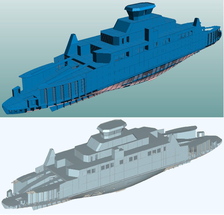
The design solution proposed incorporates a solution with a high level of topology. The designer can create the complete hull structure with a flexible approach using parameters and reference planes in a topological model from hull surfaces imported from third-party software. The design process is thus not locked inside a specific design solution. It also provides shipyards with the flexibility to use design subcontractors of their choice, which allows the involvement of the best expertise in each area in the design project.
2.1.1. Parameters
The main dimensions can be represented using parameters in the Adaptive General Arrangement tool. These parameters are defined once conceptually and are used throughout the project. The parameters can be defined as fixed values, such as the main dimensions, or mathematical formulas. Other para-meters can be used in the mathematical formulas, for instance, to define dimensions dependent on the main dimensions, creating an inter-dependency between these values. One can, for example, define a reference distance between decks dependent on the fixed value parameters for the deck positions. An example of parameter definition can be seen in Fig.1.
Therefore, all parameters are defined once and referenced throughout the entire project and can be modified at any point during the project’s life and are automatically recalculated. Changing these parameters, results in a vessel with different characteristics.
2.1.2. Reference surfaces
Further refining of the theoretical model can be done by using the parameters to define conceptual surfaces with properties named reference surfaces. These surfaces are concealed flat surfaces with properties such as thickness and material type, which are used as the topological basis of the plate definition. The actual steel structures cross-refer the reference surfaces and are given the same properties. They are updated accordingly when changes are made to the linked reference surface.
Besides the high degree of malleability, detailed engineering in the following design stage is also much faster because the plane and the properties are predefined in the reference surface.
Consequently, it is possible to define a whole topological system where altering a single parameter modifies every key construction in the ship, taking all the conditions into account.
2.2. Layout definition
How should one sketch the main layout of a ship once the main dimensions of the vessel are defined? Ideally, the creative process of the naval architect is supported by the design system. Drawing the vessel’s layout in the simplest and fastest way must be the focus of an intelligent general arrangement tool.
2.2.1. Bulkheads
To capture a complex vessel, naval architects break the design into pieces, designing on the floor and deck level. They try to create a sufficiently complete design quickly, so that all relevant requirements can be checked against the design. Designing in 2D is the best option when faced with tight deadlines. Moreover, designing through sketching helps to understand proportions, scale, and relationships that are difficult to see in 3D. Therefore, manipulation in 2D gives the most freedom to quickly create and modify the plan at the basic design stage.
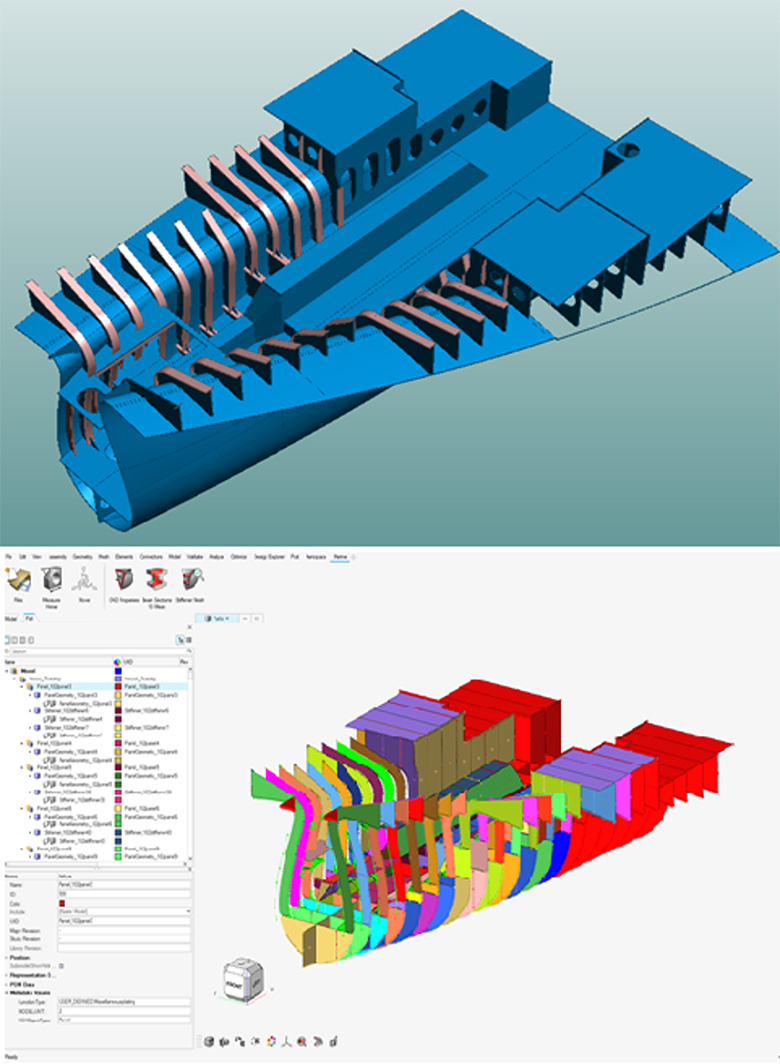
New functionality for fast design lets naval architects promptly generate a ship layout by selecting multiple drawing lines or a fixed value with step sizes. Sub-bulkheads and longitudinal bulkheads can be created by converting drawn lines at the floor or deck level to steel plates; the system builds the 3D model automatically and searches for the 3D boundaries of the steel plates to be created, as is illustrated in Fig.3.
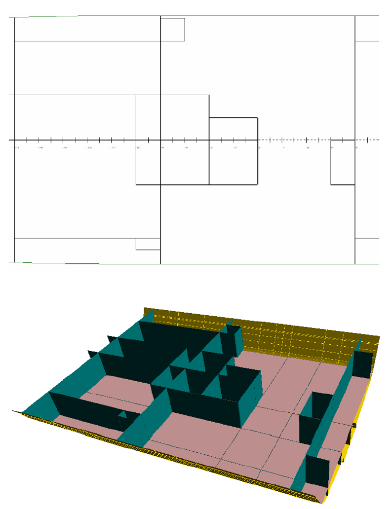
The newly created plates include construction properties; the topological behavior is essential since it allows the plates to be updated when the boundaries or the main dimensions are modified.
The generated 3D model is used directly in later stages of the design for complex changes. Because the 3D model is simultaneously created during sketching, there is a direct connection between the 3D model and the sectional views. When the 3D model is changed, these views are automatically updated, thereby saving time and avoiding errors.
2.2.2. Profiles as properties
After the main layout has been defined, the naval architect can speed up the design by stiffening the designed structure with automatic stiffening functions. The profiles as properties functionality enables the maritime architect to strengthen the bulkheads automatically in one go. The software tool automatically places stiffeners on each grid position on the selected bulkheads. When a stiffened bulkhead size changes, the system automatically adds or removes stiffeners to it depending on the new size of the bulkhead.
Besides the obvious speed gain by automatically stiffening the bulkheads, the design is further sped up due to faster model calculation, since these automatic stiffeners are considered one 3D model, not separate ones. After the general arrangement has been approved, the stiffeners can be converted into regular stiffeners for production.
2.2.3. Pillars
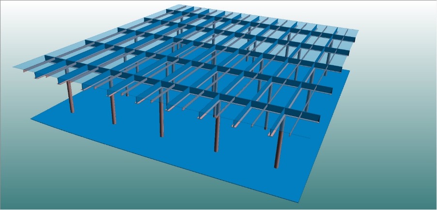
A naval architect can define pillars in a matrix, and the system automatically determines the end relations. For example, the maritime architect can establish a series of pillars in length and a series of pillars in breadth on a deck level all in one go by providing the direction and distance. The system automatically searches for the end limitations, like the deck below. When a girder is present, the pillar is automatically connected to it, Fig.4.
2.3. Weight estimation
Commonly, the steel weight in ship design software is based on adding together the data of all parts. At the initial and basic design stage, however, the naval architect creates a minimalistic design in order to deliver the proposed solution in time. The weight of the vessel is a major factor in optimizing the design. As a consequence, an intelligent general arrangement tool should assist the naval architect with a solution to estimate the weight of the vessel even if the design is not yet complete. This research paper describes a novel way to estimate the weight on the ship based on the main layout.
The midship section and the main layout are mandatory to define the basic design and general arrangement. With this information, the scantlings are determined so that the ship follows the rules. The solution for weight calculation has been extended not only to do the addition, but also to estimate the weight and center of gravity (COG) of the ship based on “reference” frames. After the naval architect has designed the mainframe, a parallel mid-ship section can be created as a fully loaded 3D space.
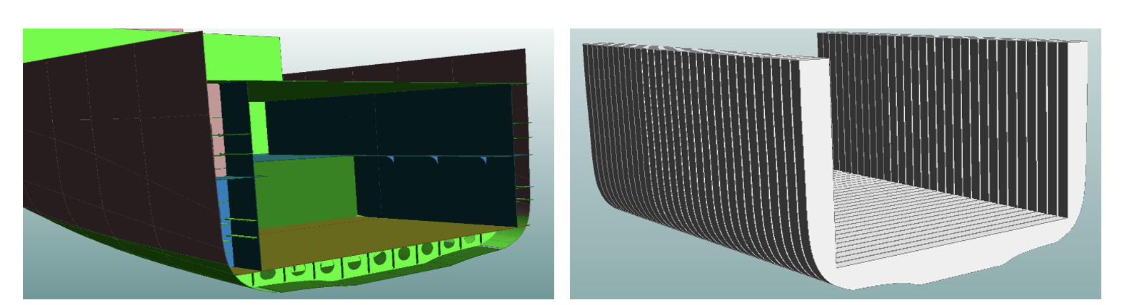
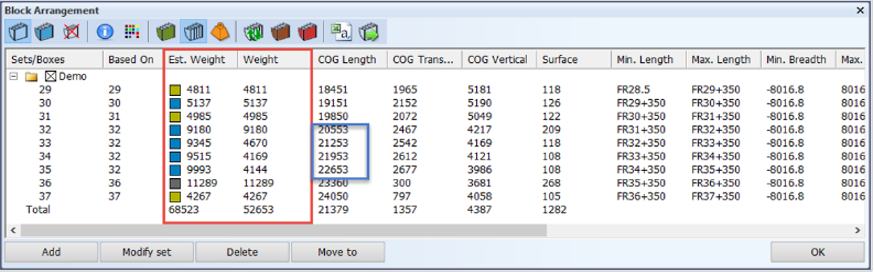
It is possible to calculate the actual steel weight and COG of the mid-ship section, the volume, and the weight of the fully loaded space, Fig.6. Based on this information, it is possible to extract the ship shape's weight per volume ratio [kg/m3]. This weight is used for other frames similar to the mid-ship.
The tool is not limited to the mid-ship section. Several reference frames can be utilized concurrently for weight estimation to achieve a more accurate estimation. The more reference frames are used, the better the results. An analysis performed on the accuracy of the results showed that the estimates provided by the tool are within a 2% difference margin compared to the actual weight of benchmark vessels. This allows us to conclude that the weight estimation method can be safely used for quick weight estimation.
2.4. Scantling analysis
To create sound and consistent structures to ensure safety and economic viability, the design must be checked against well-known rules and regulations. Several classification societies can calculate the feasibility of the design in terms of scantling choices, plate and panel thickness, and the spacing of internal frames, bulkheads, and longitudinal stringers. The solution proposed is linked to different unidirectional or bidirectional scantling tools, which reduces the time needed for the iterative early design process.
2.4.1. Cross-section approach
Traditionally, scantling calculations are done based on data from frame views. The primary data passed on to the scantling calculation software contains the description of the inner construction of the vessel and its variation along with the ship, translated to the calculator’s specific protocol. A schematic of the proposed hull structure tool and the scantling analysis tool is shown in Fig.7.
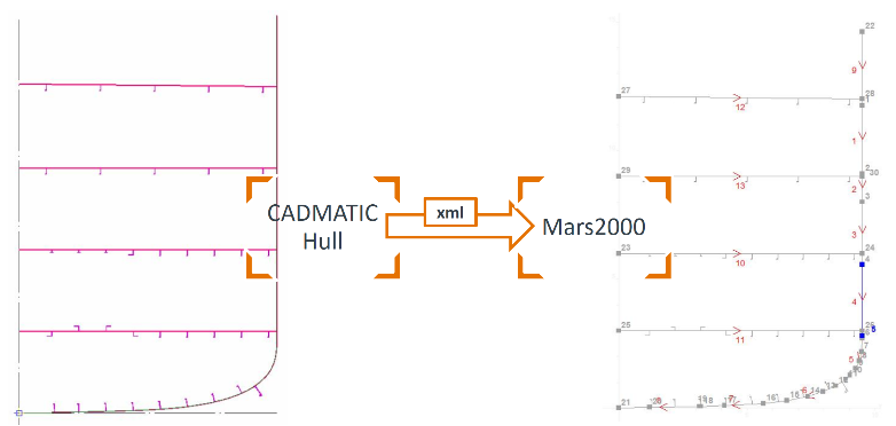
Data exported from the design system to the frame-based scantling calculator consists of basic ship information, such as the name, class notation, main dimensions, material, and relevant ship drafts. In addition, the data includes bending moments and shear force distributions. The data transfer is file-based, for example, in XML format and other standard formats such as OCX that are covered under 3D scantling calculation below. Research has been conducted with Bureau Veritas’s Mars2000 software, an example of a frame-based rules calculator tool. The data from the proposed CAD system is exported in an XML file, which is opened in Mars2000. The cross-section appears in the project window. Primary ship data can be manually modified, and the transferred values of bending moments and materials can also be corrected, if needed. In Mars2000, the user can adjust the plates and stiffeners of the cross-section of the resulting midship section that does not comply with classification rules. Possible changes in plate thicknesses and stiffener profiles are then shown to the user, who can modify the model in the CAD system accordingly. The same process interface can be used between the CAD and similar scantling tools.
2.4.2. 3D scantling calculation
To enhance the classification process, a switch from a 2D drawing-based to 3D model-based process has been researched and defined in the Open Class 3D Model Exchange (OCX), Fig.8. As described by Astrup (2019), OCX specifically addresses the needs of classification societies and shipbuilders for fully digital information exchange.
This OCX format is intended to become an open industry standard for exchanging design information between designers/yards and classification societies. In addition to optimizing the calculation process by directly interfacing with the 3D design model, all parties involved in the vessel design have direct access to the model by directly interfacing with the 3D design model. This ensures transparency and reduces the amount of work by eliminating unnecessary drawings. Having direct access to the 3D model also improves the understanding of the design.
The application of such a universal format goes beyond 3D scantling calculations. We are studying the possibility of using the model in the OCX format to perform FEM calculations. Presently, the naval architect needs to prepare a meshed model of the vessel to study the steel stresses. The Adaptive General Arrangement tool eliminates this cumbersome step by expanding the standard OCXformat for FEM analysis. Preliminary results have confirmed great potential in directly sharing the vessel 3D model via the OCX format with the FEM software, eliminating the need of meshing the model inside the CAD software.
The proposed adaptative general arrangement software ensures access to the 3D model and can read back information. With the traditional method, the design must begin with structural design software, such as the design tool mentioned, after which the model is exported to the approval software. With this bidirectional solution, the procedure could start in the scantling software and continue to the structural design software.
Furthermore, when the classification society requires changes to the model, these changes must be made manually in traditional approaches. With a bidirectional connection, such modifications can be automatically done in the adaptative design tool by importing 3D models from an OCX file.
The process described improves the drawingless strategy in shipbuilding. Seppälä (2020) proposed that there are possible scenarios for drawingless production in shipbuilding. Considering the primary driver of intelligent IT, drawings are already being gradually substituted with 3D viewers and with direct data transfer to production or manufacturing control systems. CAD plays a vital role in the substitution process by providing interactivity with data and faster access to it within change management. Design application functionality will impact how regulatory bodies classify vessels, and it would represent a significant change if drawings were eliminated.
2.5. Layout of equipment in general arrangement
During the basic design phase, heavy machinery layout significantly influences the ship's weight. Therefore, adaptability to new designs must be extended to outfitting elements. Outfitting elements, such as power, propulsion, and ship system equipment, platforms, and other outfitting steel constructions are usually added in the outfitting module. The solution proposed integrates the design disciplines so that the hull application has access to these elements via an equipment library which provides access to the outfitting database. This allows the model to be equipped with components from libraries that can be reused whenever necessary.
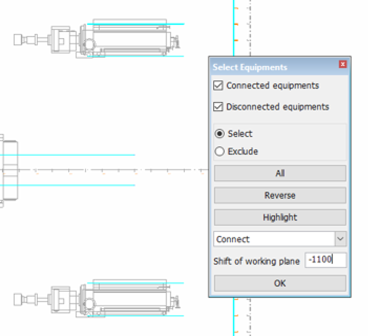
With the elaborated “Equipment Layout” function in the hull application tool, the user can insert heavy machinery, for instance, by opening the component library and selecting equipment. The equipment is displayed in the hull view and can be positioned as required. Outfitting and piping disciplines can access the same model, making adjustments or changes according to machinery requirements.
Since topology is the main factor that speeds up and automates steel creation, this property is also added to the equipment via the “Connect to view plane” function. This ensures that the circle of automatic topological behavior triggered by the parameters is applied to close the loop. The equipment is connected to the level view (i.e., level drawing) in which the equipment is added to the equipment data. Level views are related to reference planes and are thus updated when the reference surface changes, thereby updating the equipment.
3. Optimization
The design of a ship is complex, with several variables that need to be considered. In addition to traditional design factors such as efficiency, cost, ease of production, a sound and safe structure with a long life cycle, new variables are constantly introduced to achieve updated goals. Currently, an important goal is the achievement of green ships as an environmental responsibility and a sound economic investment. This requires several factors to be considered, such as low emissions, eco-friendly hull design, zero discharge, or a low acoustic signature.
Several methods to optimize ship design have been introduced, such as optimizing parametric models, simulations, or surrogates. The adaptative general arrangement tool is linked with optimization tools. A high level of integration between the design system and optimization system facilitates the iterative early design work by coupling the design of a skilled naval architect with an optimization package that carries out the optimization in batch-mode without manual intervention.
3.1. Shape optimization
Shape optimization is a factor when optimizing a vessel due to its significant impact on hydrodynamic performance and structural behavior. Changes in the shape lead to changes in length and beam, which influence the weight and resistance.
3.2. Example of CAESES
Parameter-based modelling is not confined to the CAD model but also extended to geometry modelling. Therefore, the vessel’s shape is represented by a set of variables that trigger changes in the shape when the variables are modified. Thus, due to the possibility of parametrizing both the shape and the model, one can encapsulate the most critical constraints and pass on the corresponding parameters to optimization algorithms to optimize the whole ship design.
The intelligent hull general arrangement tool can be directly connected to any optimization software. CAESES software has conducted research that provides a new hull shape for every optimization variant, Harries and Abt (2019). In addition to the unique shape, the primary dimension parameters such as length and beam are updated, and the CAD system recalculates the 3D model. It is subsequently checked whether the scantlings are acceptable, and a new weight is provided based on the updated 3D model. The optimization software then calculates the resistance of the current hull form and the CAPEX and OPEX. The cycle continues until the optimization software finds the optimal parameters corresponding to an optimal vessel design, Harries et al. (2019).
4. Conclusions
The main conclusion of this research is that there is a possibility for ship basic design optimization with a holistic approach using an adaptative general arrangement tool and integrating different tools and processes (design applications with calculation, scantling, and optimization tools). Using an adaptative available arrangement tool, a naval architect can generate various design alternatives in less time. The process is unidirectionally or bidirectionally integrated with scantlings and approval via standard formats accepted in the shipbuilding industry.
The adaptative intelligent general arrangement tool improves the design layout with the definition of the hull structure based on high topology, parametric values, and reference planes. This allows the brief description and propagation of changes, which are very common during early design. The designer leverages the generation of the 3D layout from a 2D drawing sketch while the boundaries of the hull structure elements are automatically calculated. Stiffeners are added to the model automatically as well. Changes are propagated easily, with the ability to analyze their impact on weight estimation. The iterative approval process improves the ability to interchange 3D data with scantling tools via a standard format. Finally, the adaptative general arrangement tool is linked with optimization software for simulation-driven optimization based on parametric values. Further developments and new processes will ensure a fully drawingless approval process.
Further research should include aspects of equipment layout and topology of the 3D arrangement of equipment and the accommodation of hull structure and other interoperability questions for independent design evaluation.
References
ASTRUP, O.C. (2019), APPROVED redraws requirements for class verification, https://www.rina.org.uk/APPROVED_redraws_requirements_for_class_verification.html
BRUCE, G. (2021), Shipbuilding Management, Springer Singapore, 2021
EVANS, J.H. (1959), Basic Design Concepts, J. American Society for Naval Eng. 71/4, pp.671-678
HARRIES, S.; ABT, C. (2019), CAESES – The HOLISHIP Platform for Process Integration and Design Optimization; A Holistic Approach to Ship Design Vol. 1, Springer, pp.247-293
HARRIES, S.; DAFERMOS, G.; KANELLOPOULOU, A.; FLOREAN, M.; GATCHELL, S., KAHVA, E.; MACEDO, P. (2019), Approach to Holistic Ship Design – Methods and Examples, 18th COMPIT Conf., Tullamore, pp.224-245, http://data.hiper-conf.info/compit2019_tullamore.pdf
SEPPÄLÄ, L. (2019), Drawingless production in digital and data-driven shipbuilding, CADMATIC, https://www.cadmatic.com/en/resources/articles/drawingless-production-in-digital-and-data-driven-shipbuilding/