Highlight Latest Changes
There is a new function available in the context menu when a drawing is open in the graphical window: Highlight Latest Changes. This function compares the current drawing with the last saved version of it. All differences will be highlighted with the standard highlight color.
Release Highlights 2019T3
Version 2019T3 contains VR interface to Plant Modeller, new tools for handling design and production data and numerous additions to simplify routine tasks.
Diagram
Automatic Diagram Replication
In multi-user environments, starting the Diagram application replicates the changes made by other designers, and if there are a lot of changes this replication can cause a considerable delay in the application's start-up time.
Starting from 2019T3, replication of Diagram data can be scheduled and run in the background as many times a day as needed. When most of the data can be replicated using the Service Instance, the Diagram application starts faster.

To use this feature on a site that creates or browses P&I diagrams, the site must have SQL Server installed and the CoDesigner replication enabled.

SQL Backup Included in COS Backup
The SQL database of the Diagram application can now be included in scheduled COS backups, which makes it easier to automate the backups and to ensure that the SQL backup is from the same point in time as the COS backup.

Diagram Object Color Schemes
When designers want to see object-specific information from the Diagram database, they can open the database view of an individual object or generate a listing for multiple objects. This can quickly become repetitive and tedious, especially if the purpose is to study the completeness or integrity of the design.
In 2019T3, the objects in the active diagram can be colored in different ways. This allows the designer to constantly see to which category each diagram object belongs, based on underlying data that is defined in different CADMATIC applications or even in an external data source.
For example, the color-coding can show the designer where diagram data might still be incomplete or erroneous, or what the ordering or installation status of a given component is. The designer can easily switch to a different coloring scheme—the legend for the currently selected color scheme is shown in the active diagram.
On the Home tab, the Colors field has new options for selecting a coloring scheme:
- By eShare Data – Color the objects according to object category defined in CADMATIC eShare. This category can be based on an attribute value, a smart point type, or a status tracking item that uses a Position ID attribute. In addition, it can be based on an external data source, such as a categorization defined in a Microsoft Excel file. The example below shows ordering status of components, obtained from Excel via eShare.

- By Compartment – Color the objects according to their compartment (if defined in object data).
- By Database Column – Color the objects according to values of one or more SQL database columns. The example below shows objects being colored according to values of the Description field.

Outfitting & Plant Design
Plant Modeller in Virtual Reality
In 2019T3, Plant Modeller supports the use of virtual reality glasses. In the Inspection View window, clicking Open in VR transfers the view to your VR glasses.
These features are currently supported in VR:
- Navigation modes:
- teleportation
- movement using VR controller
- movement using keyboard and mouse
- Measuring (with vertex snapping).
- Object data query.
- Improved performance by limiting the number of shown objects based on highest size/distance ratio.
Catalog Part Import from Excel
Administrators can now create catalog parts more easily by using import from a Microsoft Excel file.
In the Project Environment tool, when creating a new catalog part or editing an existing one, selecting Import from Excel opens a tool for defining the part's details by import from an Excel file. After the import, the user can complete the details by mapping the attributes in the Excel file to the Dimension Table and Catalog Part attributes. Then, the part can be stored in the library or in the project.

Enhanced Delivery Environment
The CADMATIC delivery environment has many new Standard Components that can be used in design projects.
In addition, the Plant/Outfitting online help contains a comprehensive list of Standard Components included in the CADMATIC delivery environment.
New Bending Machine Attribute
Bending machine configuration contains a new attribute, “Bending with Flange” that defines whether the bending machine supports or even requires bending with flanges.

Improved Bending Checks
Pipe bending checks have been enhanced to cover the following situations:
- Straight segment is too short
- Pipe should or should not have flanges
Pipe Geometry Ensured in Bending
It is now easier to ensure that a straight segment between two curves is not too short for the bending machine.
- When using the command Piping > Move Point > Move point in curve, allow angle to change, the tool suggests a bending angle that makes the straight piece match the minimum distance required by the machine.
- When moving a point in a curve, the context-menu command Use minimum distance between bends (K) allows the designer to move the curve the required distance.
More improvements for users
- Now it is possible to use the new pipe spool tools and isometric documents in the same project.
- Home > Identification Labels provides commands for showing and hiding identification labels in shaded views (now also for a selected set of objects).
- See information from eShare in Plant Modeller: Query Object Data has a new eShare Data tab that shows object attributes from eShare.

Plant Modeller Object IDs Are Now GUIDs
Plant Modeller object IDs have been changed to be real GUIDs. This ensures that there will be no object with the same ID in different projects. When creating a new project site, the administrator no longer needs to allocate a specific range of object IDs for the replica.
The old object ID tag “obi” remains accessible, but it returns the 36-character GUID value. Old scripts that reference “obi” should still work, but the longer return values might cause some issues. If you have an interface where some other system stores CADMATIC object IDs, make sure the implementation allows these longer ID values to be handled and stored in the target system.
Same Piping Objects in Plant Modeller and in COS
Plant Modeller used to model piping objects using a special "PIPE" object type. This was a kind of aggregate of real-world piping components, and one PIPE object could consist of a flange, a pipe, an elbow, and a reducer, for example. However, when the objects were stored in COS, the PIPE structure was split into separate objects, matching their real-world component division. This difference between the runtime objects and those stored in COS could cause various misunderstandings and problems, for example when a designer wanted to edit a pipe but could not check some of its elements.
In 2019T3, the PIPE object does not exist anymore - piping objects in Plant Modeller are now the same as those stored in COS. This means that also some aspects of the user interface have changed, and for example in Define Set the pick action will only pick the specified piping part. For the administrators, there should be fewer problems to be sorted out and, for example, implementing deny boxes for filtered replication should be easier now.
Hull
One License System for all CADMATIC Applications
CADMATIC Hull will replace the FlexNet licensing system with the common CADMATIC licensing system in the 2019T3 release. CADMATIC Hull version 6.1 and higher will use the common CADMATIC licensing server, the same as is used by the CADMATIC Outfitting and Information management applications. Please read the Release Notes for more detailed information.
Eagle Renamed to HullGUI with Improvements
Eagle has been renamed to HullGUI, and some improvements have been made. The overall speed has been improved. HullGUI also remembers the window size and position from the last Hull session, and resizing the screen now works more smoothly.
Improvements in Basic Design
Estimation of Weight and COG
Flexi Weight
The mainframe and the main layout are mandatory for defining the basic design and the general arrangement of a ship. With this information, the scantlings are determined to ensure that the ship follows the rules.
The steel weight in CADMATIC Hull is based on summing up the data of all parts. A quick estimation based on just a few parts has not been possible. Therefore the Flexi Weight tool in the 3D-Show application has been extended with estimation of the weight and center of gravity (COG) of the ship based on the so-called reference frames.
Flexi Weight calculates the actual steel weight and COG of the midship section, as well as the volume and the weight of the completely loaded 3D space that was created in the basic design phase. The tool calculates the weight per volume ratio (kg/m3) taking into account the ship shape, and uses the weight for the other frames that are similar to the mid-ship.
The tool is not limited to the mid-ship section: Several frames can be used as reference for weight estimations. The more reference frames are used, the more accurate the estimation.

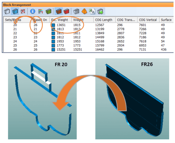
In the example above: the estimation of block area 20 is based on block area 26.
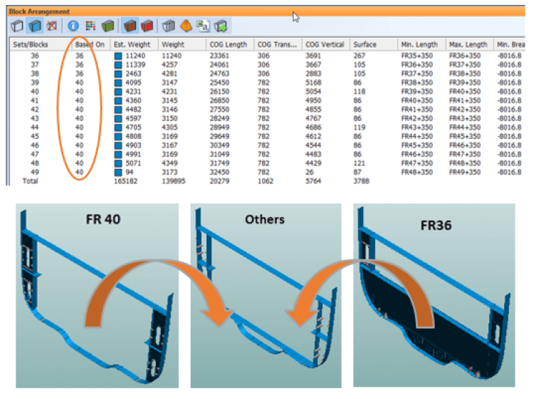
In the example above: the estimation of all block areas is based on block areas 36 and 40.
Hull Construction
Bulkheads Below a Plate
Bulkheads can now be created below a plate in the view in the 3D-Contek application. This feature is especially beneficial for basic designers for creating bulkheads under decks. It is possible to create bulkheads horizontally, vertically, and by line. The bulkheads' relations to other construction are detected automatically.
This feature will be further developed. We aim to add more the flexibility, for example the possibility to add profiles as properties of the bulkheads. You are welcome to give us suggestions for improvements and other feedback on this feature.
The following is an example of the By Line option. Bulkheads are created along the lines drawn with the line drawing function of Hull.
The bulkheads are created in the line selection order, and the resulting bulkheads are all related to each other:


New Features and Improvements in Detailed Design
General
Compare Tool
The Compare tool now includes shell views in comparisons.


Hull Construction
Face Plates in Sketches
In cases where a face plate is on multiple plates, all the related plates are now marked in the sketch, including the main plate.

For rotated face plates, the rotation angle is now shown as a marking in the sketch, making it easier for the production to position the face plate.
Presentation of Face Plates in 3D-Show
Face plates on multiple plates are shown in the 3D-Show application as well. The end types are not shown for bent face plates, however.


Presentation of Rotated Face Plates
Bevels are taken into consideration when a face plate on multiple plates is rotated. The position of the face plate in the drawing is adjusted according to the bevel type.
Join Face Plates Function and Change Main Plate
Face plates can now be joined. It is also possible to change the main plate of a face plate.

Split Face Plates Function
The user can now define in the System Management application which end types are assigned to the new face plate ends when a face plate is split. By default, type 0 will be used. The end type setting should be changed if type 0 is not available.
Shell Application
Extra Jig Information
There is now more pin jig information available in the jig view:
- Shell plate corner points of each shell plate are presented in a table, with the shell plate part numbers.
- The minimum box in length and width is presented, along with two pin distances, as well as minimal and maximal pin heights.
- Grid plane angles in three directions are included. The angles are calculated in a view which is perpendicular to the jig plane and the grid plane. Each plane gets an angle in degrees and grads.


Jig Plane for One Shell Plate
It is now possible to create a jig plane for just one shell plate.
The Template tab also now has separate commands for creating templates and jig planes.
Aligning Models in Sheet Drawings
Models in sheet drawings can now be aligned by selected corner points. The user can move one model next to another model, rotating it at the same time. This feature is useful in showing production personnel how models should be connected to each other, for example. This function is available in the context menu that is accessed by right-clicking in the graphical window.

Use case:
- Import all shell plate DXF files.
- Create a new sheet.
- Insert the shell plate models.
- Use the Align Models function to move and rotate the models as desired.

Template Marking Symbols
The template marking symbols in the template sketch are now mirrored if the template is mirrored over the center line. They have the same direction for port side and starboard. This makes it possible to use fewer wooden templates as one common template set can be used for starboard and port side shell plates.
Example: Template Symbols on Shell Plates and Templates. The template indication symbols are mirrored from the starboard plate (at the bottom) to the port side plate (at the top).

Improved Shell Plate Template
The shape of the template is extended outside of the template border with a small line that has the length of one grid step size. An extra dimension line is also added for the extension line.
The Templates contour perpendicular to sight plane option should be selected when creating templates to ensure that all the dimensions in the template sketch are presented correctly.
Also, the template table in the shell plate template sketch has been improved by adding one extra column containing the height of the template outside the plate contour.

Production
Improvements for Work BreakDown Sketches
Selecting parts for work breakdown sketches is now possible also in Hull Viewer, not just in reports. All the parts selected in Hull Viewer will appear in one sketch.
The user can also now freely select on the block level from which work breakdown branch to start labeling. Items can be labeled on more than one level below the branch.


Information Management
eShare
Enhanced navigation with maps
The eShare administrator can upload 2D DWG drawings as maps. A map can cover, for example, a ship’s deck, or a plant’s areas, such as the floors or zones, or even the site.
Maps help the user navigate the model, locate specific areas, such as a ship’s compartment or a plant’s zone, and find markups and smart points in that area. Viewing the model in 2D format can help the user perceive his or her current location in the model. The user can jump to a certain location in the 3D model by clicking the map, or access the location of a smart point or markup in the 3D model to view the details of the smart point or markup.
The user can also use maps to analyze the status of the project by checking how many smart points and markups there are in a certain area, and what their status or type is. This can help the user, for example, identify areas with an exceptional number of issues, or check if all issues in a certain area have been solved.
Scanner locations of point clouds are also shown on the map, which makes it easier to navigate to the correct location, even if the 3D model is incomplete or not available.

Point clouds
eShare users can now see point clouds as points in addition to the previously available panoramic pictures. This allows the user to move freely in the point clouds and between the panoramic views and still see the point cloud, without having to save the point cloud files on every user’s computer separately. Points are loaded from the server dynamically when the user moves in the model to show the nearby environment in finer detail and clouds that are further away in a less accurate manner.
The point representation of the point clouds helps users maintain the sense of direction and location while moving between scanner locations. It also allows them to see smart points and markups in their correct context even when the user is not viewing the model from the scanner position.
REST API Adapter
eShare’s new REST API adapter allows eShare administrators to configure the integration to a large number of external systems to retrieve additional attributes for objects, show externally provided data as a coloring or as a hierarchy, or to access project documents. The new adapter substantially reduces the time needed to make an integration with systems that provide a REST API because custom development is typically no longer needed.
eShare and eBrowser
Improved scalability through limited memory consumption in eShare and eBrowser
The user can limit the memory consumption of the 3D geometry, allowing the use of larger models in computers with a limited amount of memory. If the full model cannot be shown with the amount of memory specified by the user, eBrowser attempts to keep only the nearby parts of the model loaded in fine detail.
This means that eShare in Internet Explorer can now use the same 3D visualization engine as eShare app, resulting in better visual quality, smoother motion, and faster response to user actions.
eBrowser
Combining 2D drawings and 3D models in eBrowser
The user can import 2D drawings and 3D models in eBrowser in DWG and DXF formats. Importing 3D DWG files allows combining models from different sources in a multi-CAD environment, making it for example, possible to check for clashes between disciplines, and allowing the coordination of work more efficiently between subcontractors who use different CAD tools. Importing 2D drawings allows, for example, combining the 2D plant layout to the 3D model, which improves the readability of the model and adds information to it.