
Optimization of electrical design via digital thread
Posted on July 22, 2020
Most electrical projects in shipbuilding are still conducted with 2D tools. A complete and database-oriented solution for electrical design in shipbuilding can be achieved for more efficient electrical design, installation and change management. The solution allows project work to be carried out concurrently in the ship lifecycle where electrical design is fully integrated with the ship product model, thereby creating a digital thread. The challenge is to provide a complete electrical shipbuilding solution that is connected to other ship project applications and that can be used efficiently considering the different working environments of shipyards and subcontractors.
Shipbuilding has evolved and much greater electrical demands have been placed on ships in recent years. An electrical project done by a subcontractor 10 years ago, for example, a small vessel in a shipyard devoted to fishery vessels, tugs, etc., may have required 3 000 hours of electrical engineering and mounting. Today, the same project would require 5 000 hours. Similarly, a 40-meter fishery vessel with 10 000 meters of cables constructed ten years ago, would have 30 000 meters of cables today.
Modern ships require increasing amounts of larger equipment, which in turn necessitate more cables, some of which are very expensive. A current medium-sized ship project could have 20 or 30 very expensive cables, each of which could be 200 meters in length. The accuracy of the cables thus has a relevant cost impact on the project. In military projects, the number of cables is even higher.
Societal demands impacting electrical requirements
The 21st century has seen a revolution in technology and communication, which has also affected shipbuilding heavily in different ways. People want to navigate and work in a secure and healthy environment, regardless whether they are on a vessel for work, travel, or pleasure. Environmental factors come with their own set of requirements while related retrofits and conversions introduce new challenges.
Operation demands
Ship operation is subject to electricity, almost nothing is done manually onboard a vessel nowadays. Propulsion, navigation, controlling, operation activities, weapons management, automation, communication, etc. are the main activities that require electrical and automation control. Robotization in operations and maneuvering, unattended engine rooms, as well as automation in ship command and on control bridges have introduced further challenges.
Interior ship communication incorporates other electrical requirements: notifications, warnings, interior telephone connections, data and voice, while new power systems demand more electrical power, for example, the introduction of new batteries. Classification societies have also introduced new strict regulations, while shipowners add their own.
A switchboard on a small ship may have had 4 cables and a 3 push-button in the past. Today, the same ship has very complex switchboards full of automation controlled by the ship command bridge. Everything has signals, sensors, and control systems, which implies great use of cabling for powering, automation, and control and for measuring pressures, temperatures, etc.
At another level, navies demand a great number of complex systems; everything is integrated in very secure environments with a very large number of cables and interconnected electronic components. Exhaustive penetration management and cable transit control is needed with extensive definition of attributes and details, for example, in watertight bulkheads. There are even more complex electrical needs in submarines, where each cable is defined in 3D in each transit, one by one.
Digital twin concepts come with unimaginable electrical and automation demands. These demands may reach maximum levels on unmanned vessels.
The increased level of electrification required by all these operational demands means that kilometers of cables are required inside a vessel. The cables are expensive and have a significant cost effect.
Shipyard demands
Shipyard demands for electrical projects depend on their capabilities. Some shipyards develop their own electrical projects, others subcontract all electrical tasks. Shipyards usually subcontract electrical mounting tasks. Small shipyards do not do any electrical projects in 3D, not even cable trays. Some shipyards develop and dimension the cable trays for space reservation and maybe route some important cables.
Naval shipyards, on the other hand, require software with security restrictions and the use of the high-end technology.
In general, shipyards need data for production but also for mounting. It would be more efficient to allow mounting staff access to a 3D product model for a better project understanding, measuring, quality approval and status tracking than simply providing them with a large amount of paper drawings.
Design company demands
Design companies are starting to use electrical integrated systems in their ship electrical projects. Their challenges include the need for efficient tools to do quick design and openness to be able to work with different shipowners and shipyards. They also need to comply with strict regulations and have the approval of regulatory bodies.
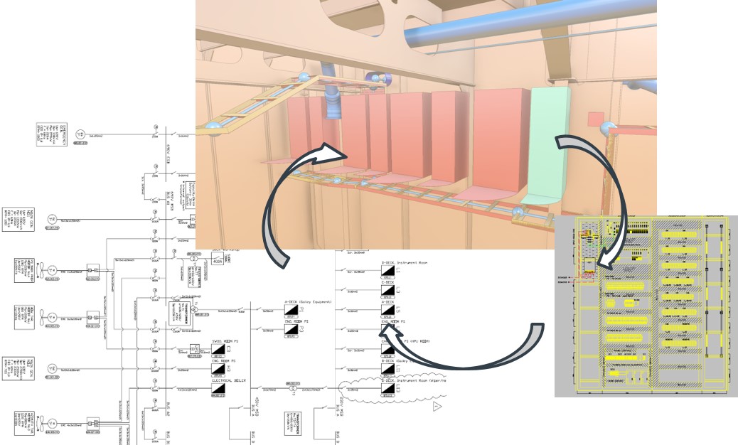
Figure 1. Integration of schematics, 3D model and layouts.
CADMATIC’s electrical software solution
CADMATIC's electrical solution is database-oriented and based on two applications, CADMATIC Electrical and CADMATIC Outfitting and Piping Design.
CADMATIC Electrical handles the electrical project in the early design stages, covering part and cable catalogues, schematics, general arrangement layouts, automatism, signals management and outputs.
CADMATIC Outfitting and Piping Design continues the electrical process with the generation of cable ways in the 3D model with the rest of the ship project model, cable router management, penetrations management and production outputs.
CADMATIC Electrical General Webinar CADMATIC Electrical Technical Webinar
Concept design
Preliminary electrical design starts by taking the following concepts in consideration: General Arrangement and other inputs, Electrical calculations, and drawing and output generation
At the beginning of a project, the ship general arrangement, main equipment and systems and electrical consumers in different operation levels are the input data to start electrical design. Data accessible from other projects needs to be easily reused in this phase. Calculations are done to dimension the electrical needs at this stage. CADMATIC has some calculation functions and allows interfacing with other calculation tools, for example with Dialux, a leading software for lighting design.
Circuit calculations and tools for the sizing of electrical elements are critical aspects. At the beginning, only power-cable switchers for the main engine, generators, etc. are dimensioned. Most of this information is sent by the engine suppliers. Electrical voltage drops are possible, considering as critical the maximum drop limits. Short circuit current can be calculated too. Another calculation is the length estimation for cables.
Cable protection needs to be checked for each circuit and considering its use, together with the characteristics and distance to other cable types.
Electrical outputs during the preliminary design stage need to be generated quickly, with automation of drawing generation and standard and customized reports that can be regenerated. CADMATIC product databases are compatible with Excel and also DWG, DXF, IFC 3D models can be used.
Basic and functional design
System definitions
At the beginning of a project, the main systems and equipment are defined. The suppliers of the main equipment send the information and details including electrical connections, cables, signals, etc. This includes the definition of the systems and other related equipment, such as control equipment, pumps, etc. The main switchboards are defined with this information.
The definition needs to be done so that it is consistent with the rest of the design needs. This is not an easy task as new equipment, duct lines, pipes and other elements are added to the project, and affect the electrical dimensioning.
For example, only changing one piece of equipment can impact and change pipes, cables, cable tray sizing, etc. The purchasing of a piece of equipment from one supplier or another impacts water services, refrigerator services, pipes to the equipment, cables, etc.
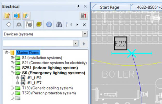
Figure 2. Product tree organized according to systems.
Catalogue Book
The material catalogue and book of unique sets of standards is expanded and populated as soon as the project evolves with more and more elements and details about equipment, fittings, and cables.
The list of elements includes equipment, pipes, ventilation lines, instruments, fittings, foundations, supports, cables, equipment instruments, electrical fittings, valves, and any other element that needs to be electrified.
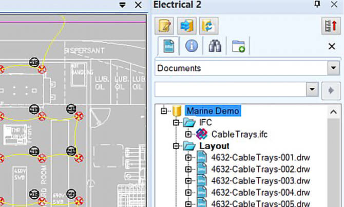
Figure 2. Arrangement of documents and lighting layout.
Schematics
The diagram tool is the main engineering application when defining the basic design electrical project. In this application, equipment, connections, the cable type needed, characteristics and section, and occupying a certain volume are defined.
Diagrams can include electrical systems, lighting, switchboard schematics, etc., including power, control and instrumentation diagrams.
Complex projects need many schematics, for example, 200 diagrams in an offshore accommodation standard ship. Schematics are linked to the 3D model in an intelligent way.
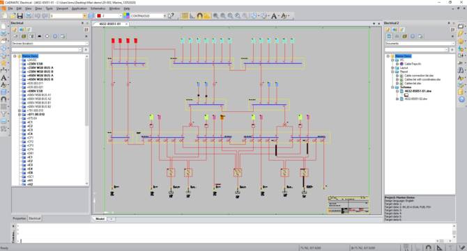
Figure 4. Example of an electrical diagram.
Layouts
The space for large equipment is defined. After that, electrical control switchboards and the main engine control switchboard are defined.
CADMATIC incorporates layout capability for switchboard layout generation.
Lighting is specified and used in line diagrams but also can be positioned in general arrangements of the vessel easily, for example, in deck drawings.

Figure 5. Arrangement detail of propulsion drive motor and control systems.
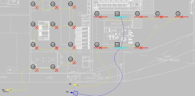
Figure 6. Lighting arrangement drawing.
Cable definition
Cables are defined in all design stages. At the very beginning of the project, the most important power cables are defined for the main engine, generators, etc. Normally, this information comes from the suppliers of the engines and does not change during the design process.
The rest of the cable definition is defined afterwards, as soon as other equipment is defined in the project. Some cables are still being installed even after the vessel has set sail.
It is particularly helpful for massive loading of information to create scripts to create new cables.
Early 3D model
In the early design stages, it is possible to position relevant equipment in the 3D model. The level of detail at this stage depends on the project. The benefits of starting an early 3D model are the accuracy of data, single access to data, collaborative design environment and reuse of data in further steps.
From an electrical point of view, some space reservations can be done in 3D in the beginning as well as preliminary cable routing of the main systems.
In naval programs, a very complete 3D model is created during the functional design with most of the equipment and elements already in their final positions.
Basic design outputs
Basic design outputs include drawings, material catalogues, lists (Fig. 7) and reports for approval, generated automatically in a customizable way.
It is important how changes are managed, for example, the addition of new items to modifications such as changes in connections.

Figure 7. Cable list exported in Excel format.
Detail design
Integration between schematics and 3D Model
The information in the diagram is the starting point at this stage, and maybe some elements already positioned in the 3D model.
The designer positions elements in 3D following the diagram with information about specific elements, connections, cables, etc. The software guides the user to position the elements correctly in 3D.
The piping and instrumentation diagrams (P&ID) contain very relevant information for the electrical project as they have information about outfitting elements, equipment, fittings, etc. These diagrams are integrated with the 3D model so that user can follow the progress of locating a piece of equipment, valves and instruments.
Cable ways
Cable ways are based on the cable tray layout in the 3D model. The definition of cable trays types, sizes and supports etc. is a predefined administration task before positioning anything in the 3D model.
It is possible to import information from components from third-party tools and incorporate them in the library book.
Equipment can be outfitted with a service space (Fig. 8) and routing cable trays is interactive in the 3D model.
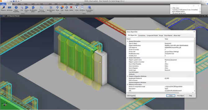
Figure 8. 3D model showing electrical cabinets and their attributes
Cable nodal network and cable routing
The electrical nodal network definition is generated following possible cable trays paths and even considering some jumps between them. Electrical items need to be linked to the network, which has predefined rules. Following this information, the cables can be routed automatically, following the most suitable and shortest cable ways. It keeps control of filling rates and interference clashes.
The cable tray catalogue defines the area that can be filled, with diverse filling schemas and the number of cable layers. The administrator can define the required distances between segregations. The definition of tray capacities includes distances between interference clashes.
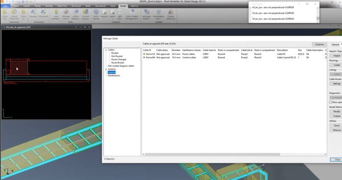
Figure 9. The fill rate on a cable tray ladder.
Service spaces are considered for soft collisions if there are items too close above the cable tray. Automatic cable ways can be filled with the calculated area, segregation distance, interference clash and different filling schemas.
Cables need to be checked for progress control and are organized according to those that are routed, not routed yet, changed, etc. in the cable manager (Fig. 10). This data is compared with the diagram as well as in the design 3D application.
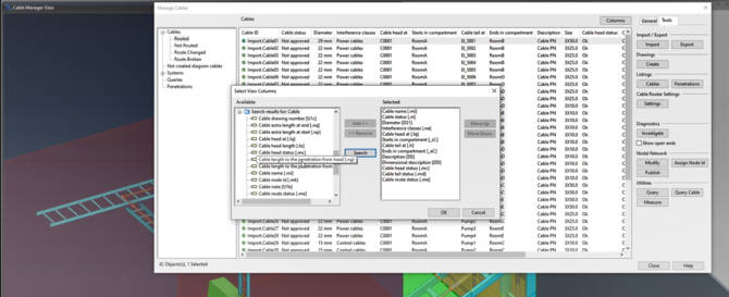
Figure 10. Cable manager.
Penetration management
Penetrations are very important and approval from the hull structure department is required for each hole. This is a critical task in watertight bulkheads. It is always useful to have standard information from market suppliers, for example Roxtec, to be used in the library electrical model.
Penetrations require unique identification. The administrator defines the types, characteristics and properties of multi-cable penetrations, their sealing elements and simple cable coamings.
The characterization and configuration of penetrations include the sizes for hole requests. A hole request is created and sent to the hull application. An online penetration manager and approval process with hull department is started in the hole manager tool.
Filling rates are controlled in penetrations. The control of cables in each penetration is also possible with a specific query.
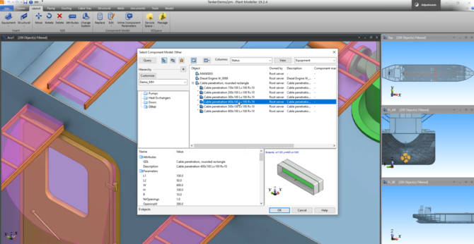
Figure 10. Cable manager.
Clash detection
It is very important to check clashes between elements, in particular, between hull structure, outfitting and electrical elements. Clashes need to be reviewed after changes in the clash manager. Information management tools with access to the 3D model can also be used at any stage to control clashes.
Change Management
The most critical aspect in ship electrical departments is managing changes. The electrical department integrates all elements in the project, managing changes until ship delivery. New cables, additional cables, different penetrations types, new structural elements intersecting cable areas, etc. are some examples.
It is possible to keep the connection of a connected pipeline when moving a piece of equipment or when moving a complete pipeline or cable tray. The geometry is adapted to its new position automatically.
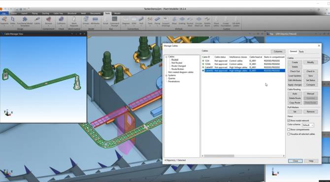
Figure 12. Cable manager after automatically rerouting a cable.
Signals
Electrical signals and control systems are defined during the detail design stage. In general, signal cables are managed in the same way as other cables. This affects how saturation checks in the cable trays and on penetrations are controlled. Reports are generated in the same way.
Cable hangers
Trays need to be fixed to the hull structure. Standard or customized elements can be used for that. There are some standard hanger and support templates and the administrator can create new ones with scripts.
Production, mounting and operation
Cable lists need to be generated including information about head and tail equipment and customized information. It is useful to run cable lists automatically and in batch mode.
Cable lengths are very important outputs. Another output is section drawings that show how cables are filled in certain segments, material information, and other related data.
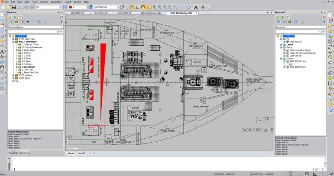
Figure 13. Drawing with electrical information.
A list of penetrations must be extracted showing the filling principle where each cable is named and located.
In general, mounting is still based on 2D drawings. For example, more than 100 workers can work on electrical mounting activities in a medium-sized military patrol vessel. In most cases, mounting workers go to the shipyard with a set of drawings and cable and equipment reports.
The mounting process is improved if a product model with integrated electrical information is used. Information management software tools can be used to integrate the electrical project lifecycle management in the digital thread.
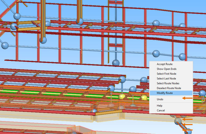
Figure 14. Viewer tool with access to electrical data.
A project review viewer, a web-based portal to access all consolidated project data from different databases or a viewer on tablets can be used to control the project and manage status tracking, planification, checking, approval processes, etc.
Conclusions
In most cases, electrical projects are still based on 2D tools. Even electrical projects done with advanced electrical 3D tools lack integration between tools, design disciplines and also between companies, as most shipyards subcontract electrical design and mounting. Much improvement is needed.
CADMATIC software is efficient with regards its electrical functionality, but also very importantly as it can be easily integrated in collaborative remote environments between shipyards, design offices, subcontractors, suppliers and mounting companies.
The use of information management solutions represents a good step forward in the digitalization of tasks to control electrical projects with other ship elements. It is advantageous to integrate electrical projects in the digital thread.
This article is a shortened and modified version of a paper that presented at the Sname Maritime Convention 2020.