
Release Highlights 2022T1
Read 2022T1 release notes and download latest version in customer portal.
Outfitting/3D Plant Design
Model tree
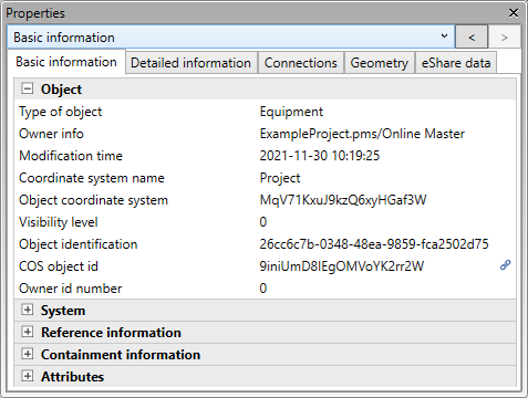
The Model Tree pane is now a fully operational data management tool that speeds up the day-to-day tasks of the designers by allowing them to focus on the objects that they typically work on in their specific design role.
The new hierarchy and filtering options allow the user to select what kind of entities to show in the model tree and how to arrange the items, so that any unnecessary items are not displayed in the tree. These customization features combined with the search function ensure that the user can quickly find a specific object or group and see where the item is located in the model.
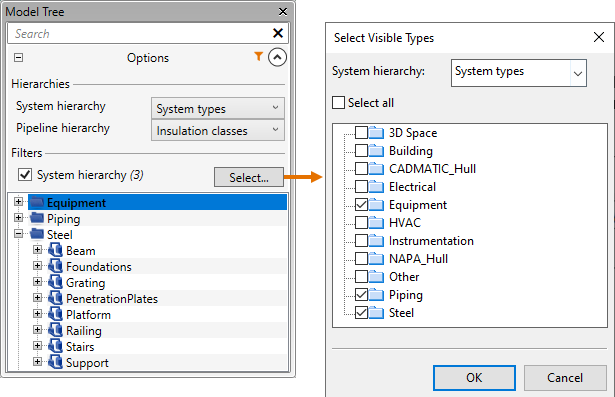
When the required object or group is found, the user can see its current check-out status from the tree and perform a check-out or check-in as necessary. Selecting an item from the model tree (or from a work view) shows that entity’s properties in the new Properties pane. You can copy a property value from the Properties pane with Ctrl+C.
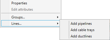
Moreover, the user is now able to create new pipelines, cable trays, and duct lines conveniently from the context menu of the model tree.
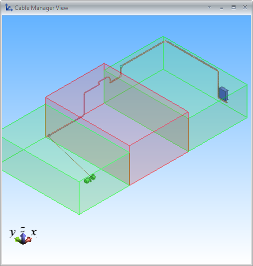
Restricted 3D spaces in cable routing
In the cable router settings, the user can now specify that specific 3D spaces such as passageways or entire rooms should not be used as pass-through spaces in cable routing. When a 3D space is defined as a restricted 3D space, the head or the tail of the cable can be in that space, but the cable cannot completely pass through the space, unless it has an attribute that overrides the restriction.
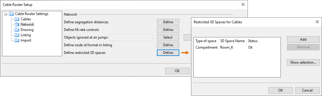
The restricted 3D spaces are shown in red in the cable manager view, and the cable routing and cable diagnostics tools consider the 3D space restrictions when searching for possible routes.
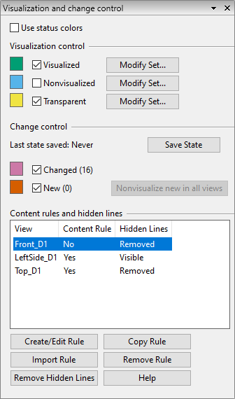
Visualization control for drawings
In Plant Modeller documents, the new Visualization and change control pane allows the user to select which objects to show either normally or as transparent objects in the drawing views when publishing a document and which objects should not appear in the drawings.
The user can save the current state of the visualization at any point, and if a designer then adds a new object or changes an existing object in the 3D model, the status-based color coding allows the user to detect the changes and decide how to reflect them in the document, for example, by adding or updating annotations or by hiding the new objects in the drawings.
In this pane, the user can also perform hidden line removal for drawing views and manage content rules that allow the visualization of drawing views to be managed via object queries.
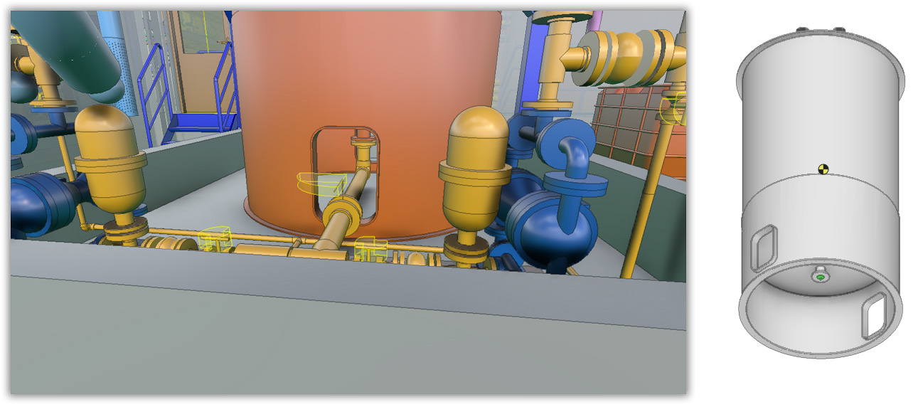
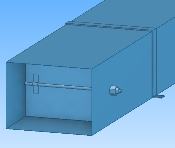
Boolean operations in Component Modeller
In the Component Modeller application, the user can apply a Boolean operation on intersecting primitives (or shapes) in order to form a new GDL primitive whose type is “Boolean”. Boolean operations allow the user to cut one object with another, to create a union of two objects, or to form an object from the intersection of two objects, using any of the existing primitive types as a source object.
Although Boolean operations can be seen as multi-functional modeling tools that can create basically any kind of visual shape, it is important to understand that a Boolean primitive is fundamentally different from the other types of primitives in that it is made with polygons. Because Boolean primitives are polygon-based, they are slower to process and visually less detailed in drawings than native CADMATIC primitives. Therefore, Boolean operations should only be used if the required contour cannot be achieved with the other methods.
Boolean operations can be used, for example, if you want to make a hole in a Beam primitive or a non-perpendicular hole in a Plate primitive in Component Modeller.
Boolean cuts can also help to reduce false collision alerts. The picture below shows boolean cuts that allow pipes to be routed via the hollow base of a tank – in previous versions a pipe that goes through a hole in a cylinder would cause a collision.
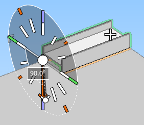
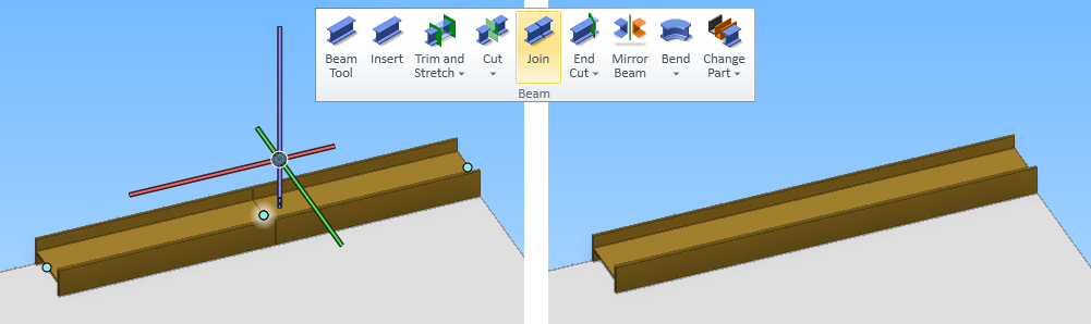
Improved beam routing
When starting to route a beam, the user can now see a cross section of the beam part and define the rotation angle and routing reference point already in the beam part selection dialog.
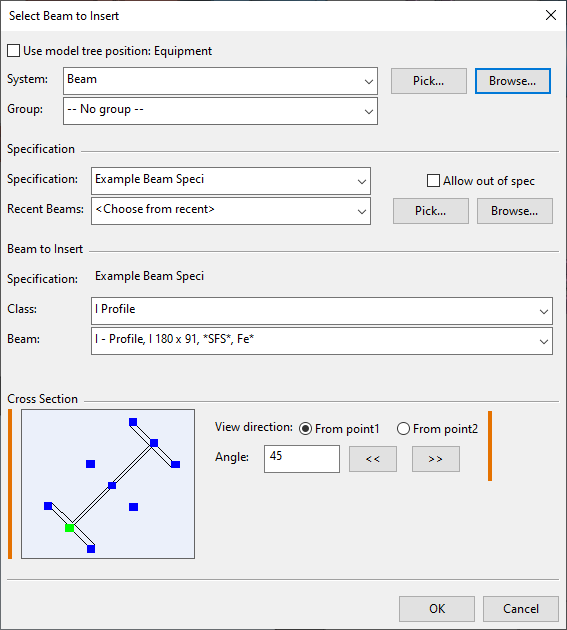
During the routing, there is improved visualization for changing the rotation angle or the reference point.
In addition, the beam tools now include a Join command for joining two beam parts that have a common beam point, same cross section and same orientation, and a separate Mirror Beam command which was previously only available via the context menu of the beam rotation tool.
Onto-line duct parts
It is now possible to insert onto-line parts such as valves and clamps to duct shapes, duct components and straight duct parts. Unlike an into-line part, an onto-line part does not cut the target duct part. Using the Resize command on a duct part also applies the command to the onto-line parts that are attached to it.
P&ID
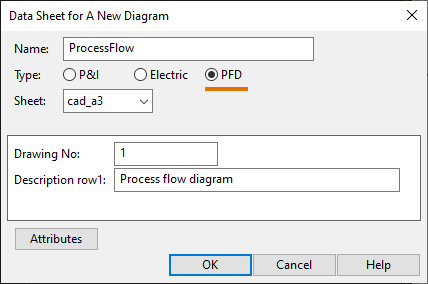
Process flow diagrams
When creating a new diagram or changing the type of an existing diagram, the type can be set to Process Flow Diagram. This diagram type is similar to a P&I diagram but it does not support topology comparison between the diagram and the 3D model.
Hull
64-bit Shape Import allows bigger hull shapes
The new 64-bit version of the Shape Import application can handle 64-bit databases. For example, it can import 64-bit NAPA databases into the CADMATIC hull database (HDB). A 64-bit database can contain bigger hull shapes which could not be handled with the previous 32-bit version.
A valid NAPA API license is required to import 64-bit NAPA databases.
Thickness direction included in NAPA Steel import
The thickness direction of NAPA main objects is now considered in the import. NAPA main objects are imported as plates or corrugated bulkheads.
Detailed information in Copy/Template Manager
It is now possible to show detailed information about the construction parts in the Copy/Template Manager by enabling the new Show Detailed Part Information setting in the System Management application. Previously enabling this feature required a special license.
Rule system extended to automatic profile end types
Automatic profile end type assignment for construction parts is now defined by using the CADMATIC Hull rule system. The rules are defined in end type configuration files. Previously the end type assignment was done in the System Management application.
Using the rule system instead of settings gives more flexibility to define the situations where a particular end type should be applied. For example, it is possible to define that the end type depends on how the profile connects to the related part.
The system automatically converts a project's previously existing end type settings to rules.
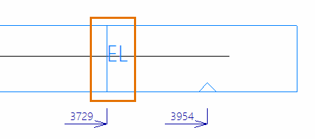
Include erection lines in profile sketches and robot files
It is now possible to automatically include erection lines in profile sketches and robot files, not just the cutting data (DXF files). These lines mark erection planes, and they are placed on the part near block boundaries.
Erection lines indicate where to stop welding near a block boundary, and thus facilitate the assembly of blocks, saving time and helping prevent errors in production.
More accurate weight and COG calculation for profiles
The weight and center of gravity (COG) calculations for profiles, including pillars, face plates and shell frames, are now always done based on the geometrical volume of the profiles. The option to do the calculations based on the profile weight properties table no longer exists.
Always using the geometrical volume in the calculations ensures that the weight and COG of all profile types are calculated as accurately as possible.
Face plates on RFHs marked on the coded part
Face plates on requests for holes (RFHs) are now marked on the coded part in the same way as face plates on regular holes.
Extended circle and arc drawing function
The Between 3 Lines function for drawing circles and arcs using lines as tangents has been renamed to Between 3 Lines or 2 Lines 1 Point and improved so that it is possible to select a point instead of the third line. The point defines a point in the arc's circumference or the starting point or ending point of the arc.
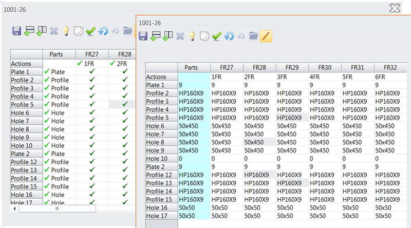
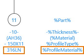
Plate part labels can show face plate material
Plate part labels now show the material type of the face plate attached to the plate, if the %ProfileMaterial% text field is included in the part label model.
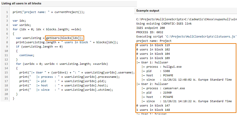
New command for Hull Clone scripts: getUsers
There is a new getUsers command that can be used in Hull Clone scripts. The command returns the users that are active in a given block in the project, as well as the processes they are using. Hull administrators can use this command in their scripts to check if there are active users in any of the blocks before saving the blocks, for example.
Information Management
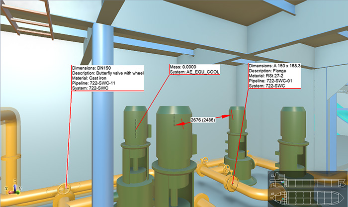
Attribute labels added to eBrowser and eShare
The possibility to add attribute labels to objects, which was previously available exclusively to eGo users, is now introduced also to eBrowser and eShare users.
This allows users to utilize the 3D model more efficiently, by using the labels to highlight important locations, measurements, and items with appropriate labels, for example during reviews. Earlier, with eGo, this functionality was especially useful in creating installation views, for example by making the necessary measurements visible on top of the 3D model to support installation work by replacing, or supplementing traditional paper drawings.
Now that the functionality is available in eShare, these installation views can be created in advance and then synced to eGo.
Draw
CADMATIC Draw 2022T1 has many new features for users.
- The completely new data extraction tool allows extracting CAD data (e.g. object and symbol attributes) from a drawing to an external data file (e.g. Excel).
- In the new version, it is possible to use drawing units other than decimals. Architectural units are also supported when they are represented in feet or inches.
- In import, it is now possible to import DGN files.
Electrical
No 2022T1 version of Electrical
There will be no 2022T1 version of Electrical. Thus, the next version will be 2022T2, which will be a normal main release: the database structure will be updated, and the version will not be backwards compatible with the 19 versions.
2021T3, the latest update 19.0.4 + Patch
For version 19, an update (19.0.4) was released on January 26, 2022. This revision will be complemented with a patch in February. The patch will include some small improvements, and enable integration with several different Plant Modeller versions (2021T2, 2021T3 and 2022T1). If the Electrical and Plant Modeller versions differ, the user gets to choose the version for integration.
Sneak peek: Group renewal
The 2022T2 version will include a completely renewed method of handling groups and feeders. Both the under-the-hood features and the user interfaces will be renewed. However, all the changes aim at one thing: a better user experience.
Benefits for the user
From the user’s point of view, the renewal has explicit goals:
- Improved user interfaces
- Showing the same cable in two different distribution board schemas
- Creating groups with several rows
- Creating several busbars in one distribution board
- Creating several incoming feeders to one busbar
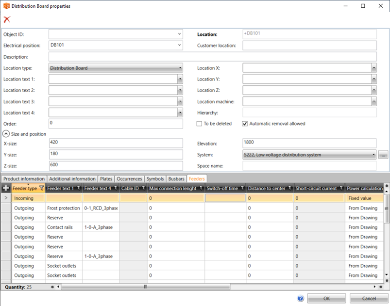
Distribution boards
In Electrical, distribution boards are location objects. Locations and distribution boards have had their own user interfaces – in the future, there will only be one user interface, listing distribution board busbars and feeders as well. Moreover, distribution boards can include several busbars, in which case they can be centrally edited in the familiar database tool. Changes will be updated to all the necessary schemas with technical details of the edited busbar.
Groups and feeders
Technically, the group mark will undergo the biggest changes. The old groups are changed to incoming and outgoing feeders. If necessary, one group can then include several feeders. The user interface has nevertheless been kept simple; you can manage both the group and its feeders in the same dialog. The feeder type allows you to manage all the cables in the distribution board with the same familiar function.
Project conversion is automatically taken care of when updating from version 19 to version 22. Therefore, old projects can be moved to the new version of Electrical and work can be continued utilizing the new features.
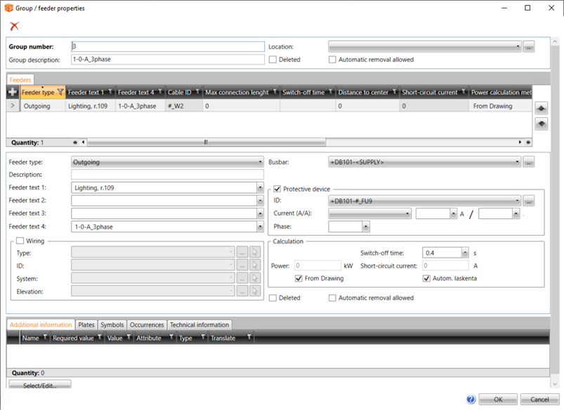
Furthermore, protective devices can be added for feeders. This means that the protective device will create a device in the database, and an occurrence of the device can then be inserted into the schema. This allows presenting devices related to feeders in separate documents, in addition to which the database structure will be more realistic.
Overall, the group renewal will bring lots of possibilities to the 2022T2 version. The renewal also makes it possible to continue developing the group and feeder functions further.