
Release Highlights 2022T3
Read 2022T3 release notes and download latest version in customer portal.
Outfitting/3D Plant Design
Common insertion method for standard components
Inserting of Standard Components to pipelines is easier as the user no longer needs to select a different command depending on whether they want to insert a component into line, onto line, or as outlet, but now all can be done with the same insertion command. The tool guides the user in completing the insertion process and, for example, an instrument outlet is automatically placed on the outer surface of the pipe. After defining orientation and rotation, the designer simply needs to slide the component along the pipe to its intended position.

Also the old, separate commands are still in the context menu for those users who are accustomed to using those.
Production checks for piping isometrics
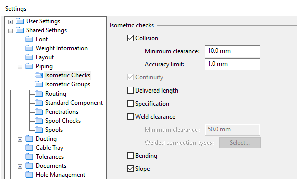
The project administrator can enable various tests and checks to be run on all isometric groups: collision testing, continuity check (always on), delivered length check, compatibility with specification, weld clearance check, suitability for bending, and slope ratio check. These checks help to ensure the manufacturability and installability of the pipes.
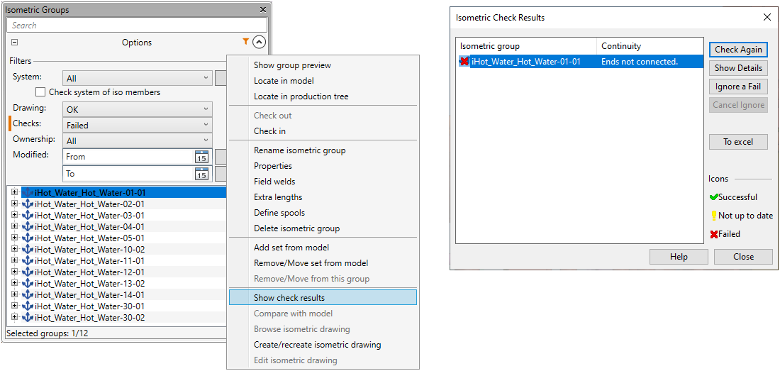
In Plant Modeller, designers can filter the list of isometric groups based on whether any checks have failed. From the group list, they can open a summary of check results, for one or several isometric groups at a time, and look at each problem in detail.
Slope ratio adjustment for pipes
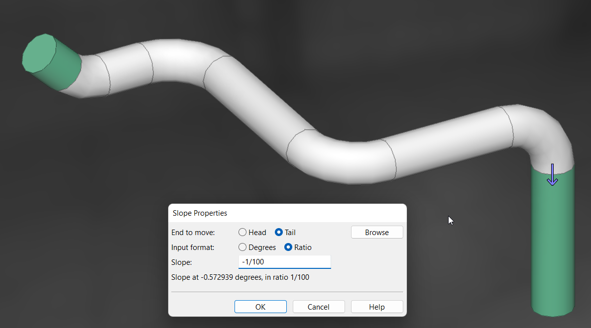
Upward or downward sloping is now easy to add to piping by adjusting the slope angle or the slope ratio of continuous piping parts. The program tries to implement the change by only modifying the straight piping parts and warns the user if any connections would break as a result.
Moreover, isometric checks (new) and pipe spool checks can now check whether the piping meets the minimum design slope or whether the sloping might form traps inside the piping.
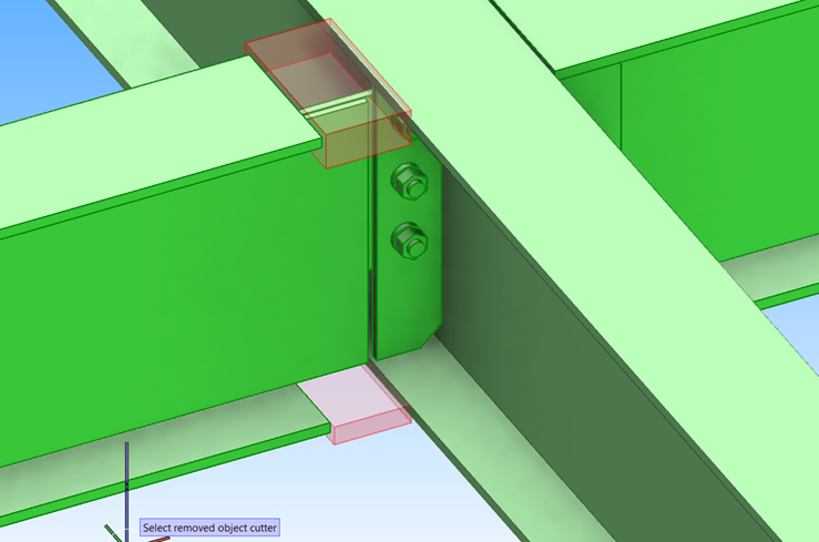
Improved moving of objects
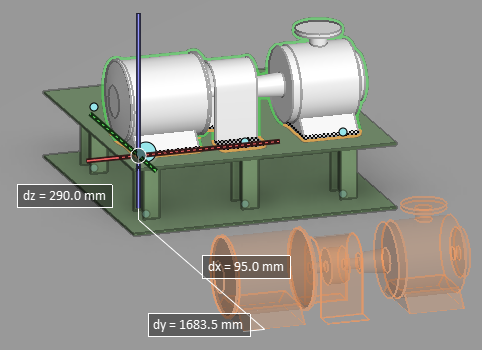
Moving model objects is more intuitive now. There is an animated preview of the objects that are being moved, constantly displayed measurements, and optional 3D ortho that limits the movements to the axis directions.
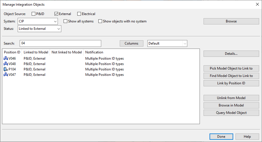
Improved management of integration objects
The Manage Integration Objects dialog has an improved user interface that makes it easier to find specific integration objects that have been imported from different data sources. Moreover, EDM objects now support transformation, which allows the associated 3D model objects to be automatically placed in the correct locations.
IFC import and export
Cadmatic beams can now be imported from IFC files that have been exported from, for example, Tekla Structure. Cuts and holes are imported as Boolean cuts, and the beams are fully editable in Plant Modeller.
IFC export from Cadmatic now uses an improved IFC hierarchy structure, supports an additional IFC schema (IFC4), contains more IFC metadata, and allows primitives to be exported as solids.
Together, these improvements enable cross-platform modification processes where beams are transferred to third-party software in IFC format and brought back as native Cadmatic beams.
New features and improvements in drawing tools
2022T3 has various new features and improvements related to creating and editing drawings:
- Background color of document editor can be changed without having to customize the project’s color palette.
- Plant Modeller drawings can be created and opened from within another drawing.
- Order of pages can be changed by moving a page to another location. Document’s preview image is now always generated from the first page.
- Drawing views can be renamed.
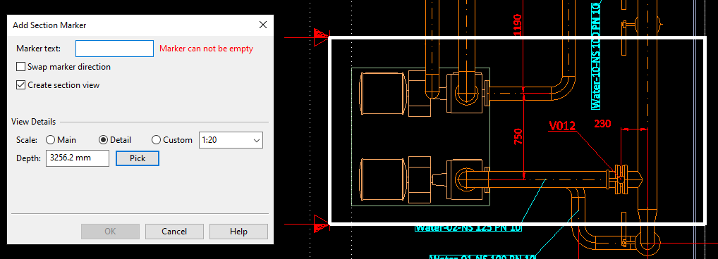
- Plant Modeller drawings allow inserting section markers and creating a section view at the same time.
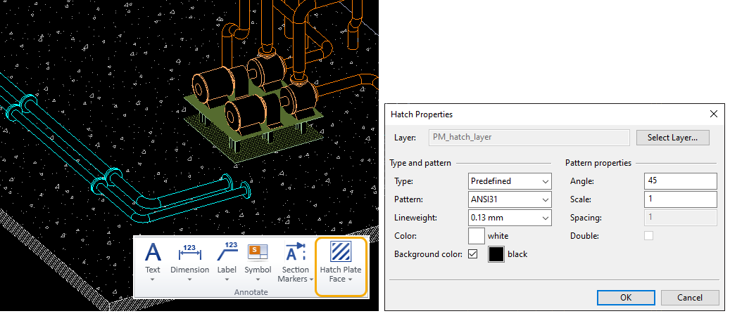
- Plant Modeller drawings allow the hatching of model objects, using predefined or custom hatch patterns. A different hatch pattern can be applied to each separate face of a plate object. Existing hatches are easy to change by applying new hatch properties, also to multiple faces in one go.
P&ID
Undo/Redo
P&ID now supports undo and redo in P&ID object modification and data editing. There is also undo/redo for the sub-operations involved in inserting dimensions and revision clouds.

New drafting toolbar
The drafting tools of the P&ID application have been replaced with the new drafting toolbar that was first introduced in Plant Modeller in version 2021T2. This provides P&ID users with better drafting tools and various other improvements to both users and administrators, such as easier linetype management.
Node labels
Equipment connection nodes can now define the nominal size of the connection. There is also a new label type for creating node labels for P&ID.
DEXPI import
P&ID is now able to import and export the DEXPI format version 1.3.
Hull
New hull line type at the intersections of different hull groups
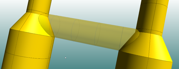
There is a new hull line type: groups intersections line. The system automatically creates identical hull lines in intersecting hull groups along their intersection when the hull shape database is updated. Groups intersection lines can be used as relations when creating shell plates that are related to shell plates located in other hull groups. This allows you to create more sophisticated shell plates, and shell plates with pipe-to-pipe connections for example.
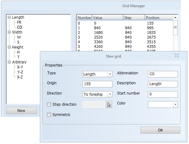
Simplified Grid Manager user interface
Several changes have been made to improve the usability of the Grid Manager and make the user interface more clear. The grid tree is now automatically expanded, and the grid details include a new Position column that shows the actual position of each grid value (as opposed to the distance from the origin).
The new New grid dialog makes it easier to create new grids. Also, the origin and the direction of the grid are easier to define. Except for arbitrary grids, the origin no longer needs to be defined as coordinates but is defined as a single value, and the direction is defined as normal or reversed direction instead of coordinates.
Also, grid values from the block's default grid can now be included in standard texts in drawings.
Features in WBD sketches for easier assembly
Improvements have been made to work breakdown sketches to make assembly easier at each production step.
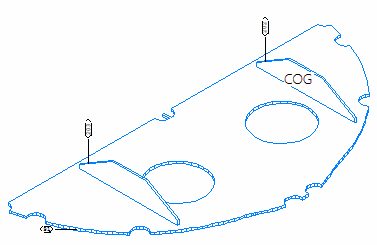
Weld lines of all parts can now be shown in WBD sketches. This includes parts from previous production steps, provided the parts are not welded in a previous step. It is possible to define the pen used for showing the previous step items.
It is also possible to show the center of gravity (COG) point of the part that is added at each production step, on that part, instead of showing the total COG point of the assembly. This applies to solid parts only.
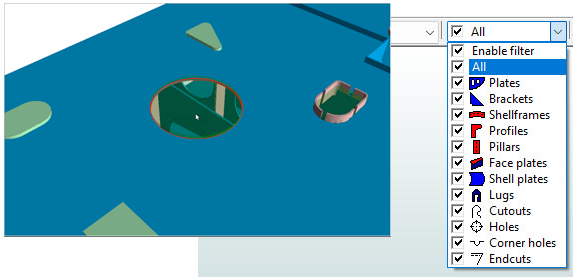
Hull Viewer enhancements
Selecting and presenting items in Hull Viewer has been enhanced. Accepted hole requests from Outfitting can be selected just like regular holes, and holes placed on several plates can also be selected now. Selection filtering now works for cutouts, holes, corner holes and endcuts as well, and the X-Ray functionality can be used for holes and bevels on plates, profile endcuts, and hull lines.
Improvements in working with the COS environment
To simplify the installation procedure, a COS user for the HCA is automatically added in the installation, similar to Plant Modeller Service.
When adding or importing an existing Hull Classic (HDX) project into Hull COS, the system now automatically handles hole request states in the project conversion process. The system generates a log file listing the hole requests that could not be handled automatically, and those hole requests can be handled manually after the project conversion with a new tool developed for this.
Saving construction to COS is now possible when Hull Viewer is open, making it quicker and simpler to save the design currently being worked on.
Information Management
Improved map in new eShare user interface
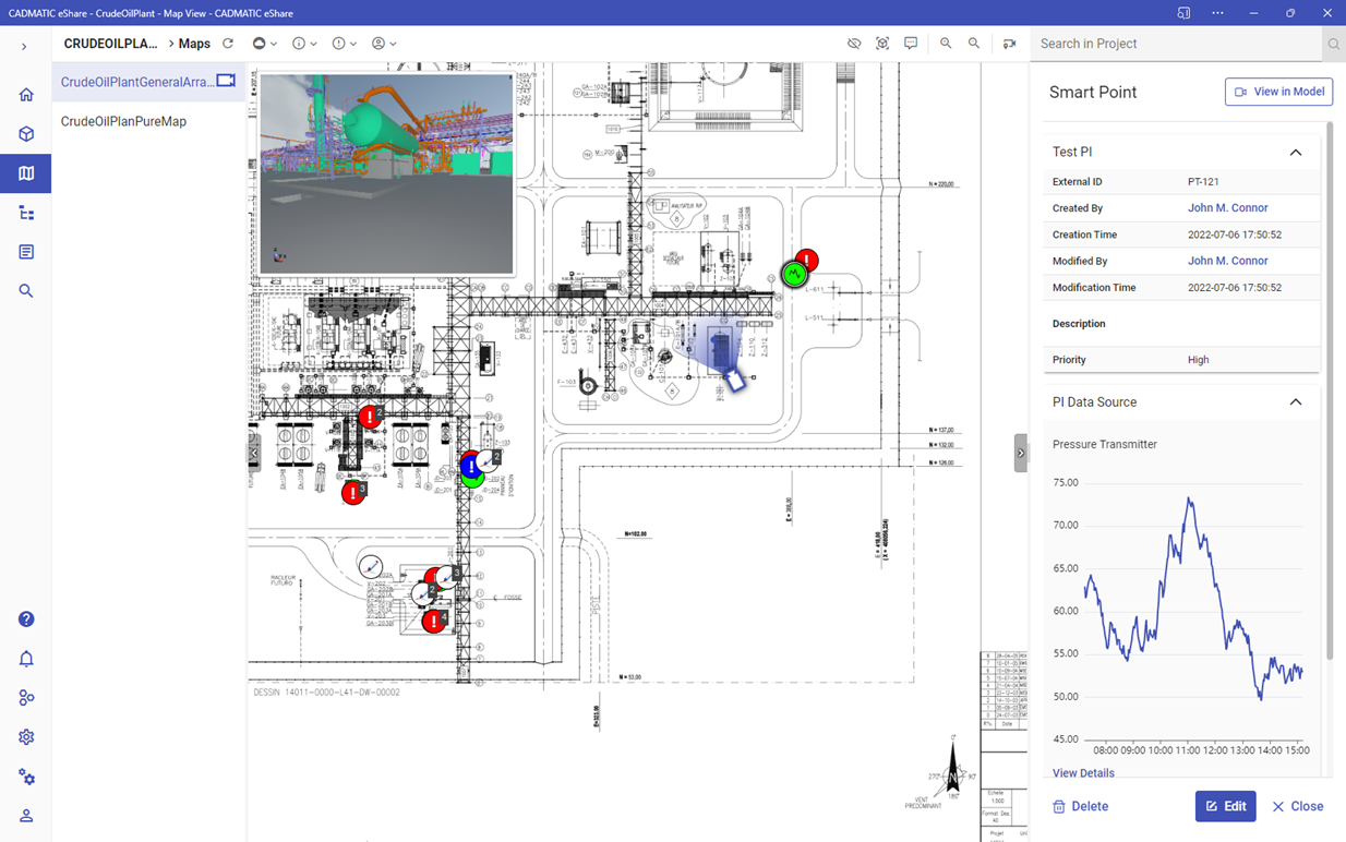
Map has now been fully introduced into the new eShare user interface with several improvements, making it even more functional with more features available at a single glance.
Camera can be added to the map by activating the camera button and clicking the desired location in the map. The camera can be moved and rotated in the map, but now moving the camera updates the 3D model automatically without leaving the map view. The changes can be seen in a preview of the model to allow an up-to-date view of both the map and 3D model side-by-side. The view in the preview window is based on the view of the current camera position. The preview window can also be hidden, if needed, or resized within certain limits. The preview window moves when the camera icon goes under it. The preview window retains the same aspect ratio as the 3D content area in model view.
Smart Points and Markups can be filtered and viewed more efficiently with the selections conveniently available in the main toolbar. The visibility of Markups can be selected based on status or type, as well as the assignee available in a separate menu. If Markups are close to each other, they are grouped on the basis of type rather than status. Smart Points can also be added, viewed, and edited immediately in map view without moving into model view, with the point properties visible in map view. The selected point is highlighted in the map while viewing or editing its details. When a new point is added to either the map or model, both will reflect the changes immediately.
The clip box can be controlled in map view and the boundaries are easier to set and see. The clip box can be moved with a handle, and it can also be resized freely from all borders or corners. The clip box state and dimensions are synchronized with the model view.
Enhanced PI adapter functionalities
PI adapter functionalities have now been further improved to offer the best possible performance in retrieving data from the PI database and utilizing it now with any type of Smart Point and also model objects in eShare. The settings in eShare now allow enabling or disabling impersonation to allow more possibilities for creating different types of client processes. The data retrieval from the PI data source can now also be automatically refreshed, the retrieval interval in minutes can be set as desired, and there is also a selection for using local or UTC time zone.
Electrical
In 2022T3, we have focused on further developing the functionality and improving the usability of the features released earlier in version 22. The usability improvements are based on feedback from both customers and application specialists. In this release, development work has been carried out in every Electrical application as well as in the installation example project.
Some of the improvements only apply to certain application levels (Premium/Basic/Lite).
Wiring renewal
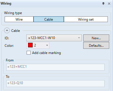
The wiring functions of the Schematics application were redesigned in the previous release, and have now been further improved. In particular, the functions related to wiring sets have been enhanced, which makes it possible to create and use wiring sets in the desired applications.
Other wiring functions have also been refined. When drawing a cable, for example, you can now select the From/To information. Furthermore, the wiring color can be changed during drawing, in addition to which the wiring function provides easy access to the Electrical settings to change the default color.
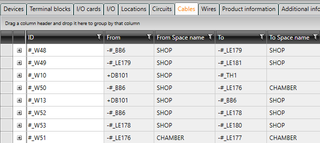
Database functions
The database speed has been optimized, which makes opening, saving, and closing dialogs via the drawing faster. In addition to optimizations, the users' needs to see various pieces of information in the database have been taken into account. For example, in addition to the From/To information generated for cables, the From/To space name can be displayed.
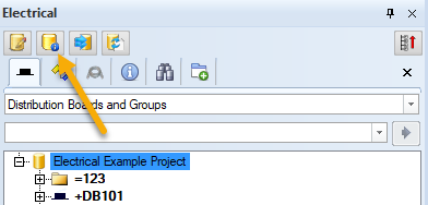
Sometimes you need to adjust project settings – we wanted to make this easier by creating a "shortcut" to them. The new button can be found at the top of the Electrical tab:
Distribution board and group renewal
The distribution board and group renewal of the previous release has been continued systematically. Group dialogs have been modified and their operating logic improved. The user's previous selections are now remembered, and for example, the 2D symbol selected for the group/feeder is automatically selected when creating the next group/feeder.
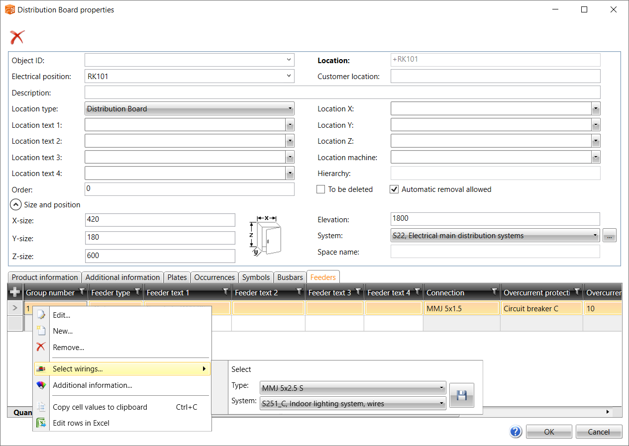
In the Distribution Board properties dialog, it has been possible to create several busbars and feeders, and mass edit some feeder information. Now the wiring of the feeders can also be edited: the user is allowed to select the cable type and the system.
Cabinet Layout
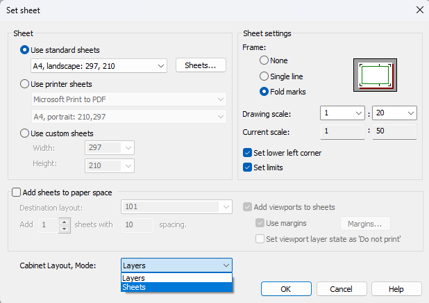
In Cabinet Layout, the sheet mode familiar from the Schematics and Distribution Board applications has been implemented.
In the past, different object types (such as devices and installation rails) have been on their own layers in Cabinet Layout. When using the sheet mode, all objects of a single sheet/distribution board are on the layer called SLEHTI instead of on top of each other on different layers. Drawing the mounting plate and door side by side is easier for the user, and it is also the most common way to present the different parts of a distribution board in Cabinet Layout drawings.
The user can enable sheet mode when creating a new drawing. The old mode is also still available.
Draw
In CADMATIC Draw 2022T3, the usability of the 3D camera as well as the shade performance have been improved. In addition, the visualization window has been enhanced with new options for switching between the visualization window and design view.