Release Highlights 2018T1
The main theme of the new version is accuracy, which is the red line across all products. Taking the smallest details into consideration and ensuring accuracy in the installation and production phases can be seen in every new feature:
Diagram
2018T1 Diagram supports Unicode symbol characters in SQL fields, visible field names, choice fields, diagram dump export and import, diagram ASCII dumps, specification field in armatures table, and position IDs.
The new version contains numerous additions with an emphasis on user experience and attention to detail:
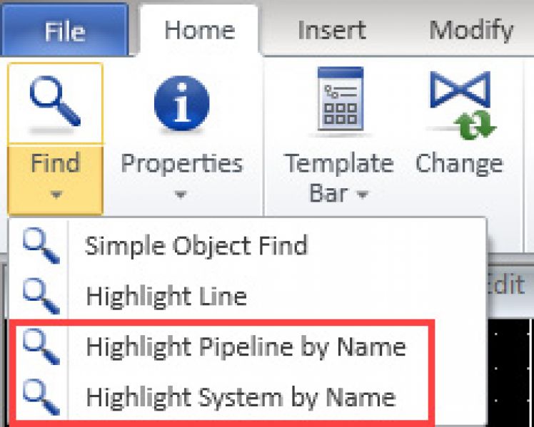
- Search Systems and Pipelines by name
- Easy to join unconnected connection lines to equipment or armatures.
- Polyline segments can be modified by moving middle points.
- The user can define the color of connectors and free nodes by using User Interface settings for Connector color and Free node color.
Outfitting & Plant Design
New UX – assistance for navigation and routing
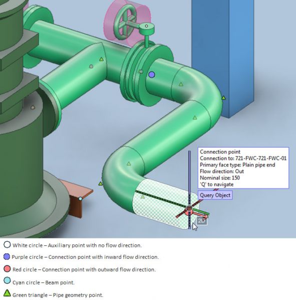
Gain accuracy in 3D design – see all points in 3D, visual cues for efficient navigation and isolate the area you need to work with on the fly.
Starting from version 2018T1, users can easily see any point in 3D: the geometry and connection points of pipes or components and structural items. The new cursor assistance visualizes the points of invisible objects in the active view. When the cursor is close to the point, it is highlighted and a navigation tip is displayed.
It is easier to define directions with visual marking of angles.
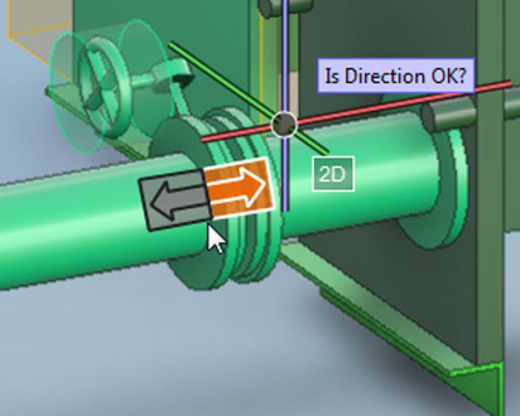
Defining directions is shown visually for easier selection
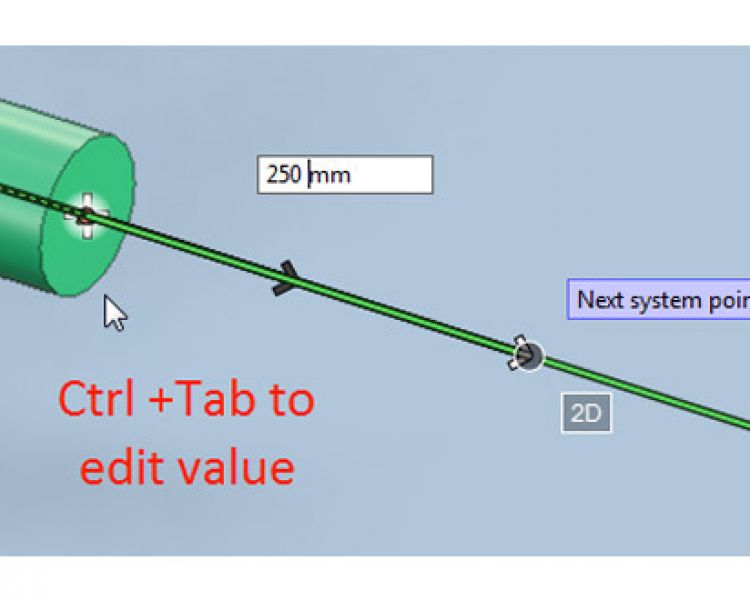
In addition to being a visual aid, it is possible to input a value for routing. For example, input the length when the cursor is constrained to the line.
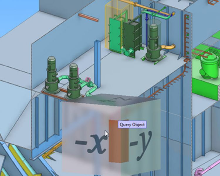
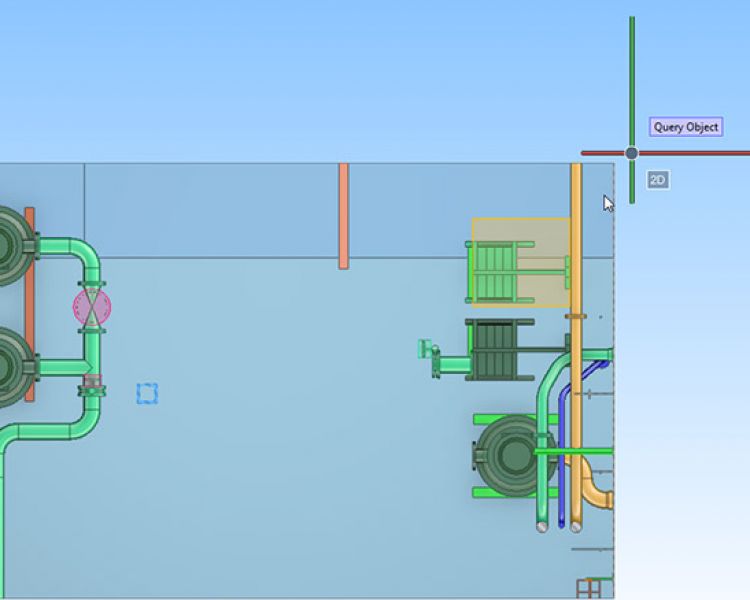
Visually set filter box limits
Pressing Ctrl+5 in a work view opens a graphical tool with which the user can edit the filter box by selecting which face, edge, or vertex of the filter box to move to the current cursor location. In views that are parallel to the main axis, the selection tool is two-dimensional, and in axonometric views it is a cube. In shaded views that are parallel to the main axis, the user can also see a preview of the resultant filter box
Outfitting
Outfitting
Outfitting
Up to 75% faster collision control tests
In version, 2018T1 collision control tests are significantly less time-consuming. For smaller tests, such as inside a block or area, or for an isolated system, the tests will be about twice as fast compared to previous versions. For extensive collision tests, such as all against all in a large 3D model, the user will obtain results up to 75% or almost three times faster
Gain accuracy in cable layout – new diagnostic tools for cable routes
Visualize open ends of cable routes
For the visual inspection of cable routes, version 2018T1 offers the option to visualize the open ends of cable trays. This allows designers to spot the open ends of cable routes at an earlier stage and to make the needed adjustments in the nodal network by adding air jumps or additional segments for trays.
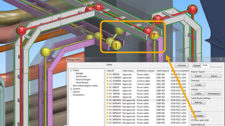
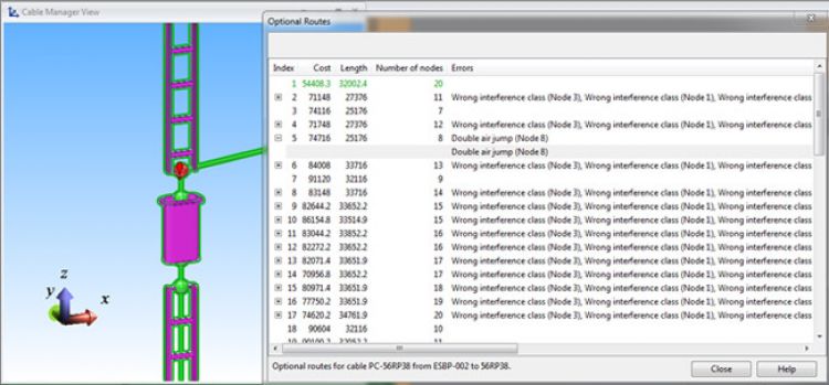
Investigate routes
Cables can be investigated to display all possible routes for the cable with information about the options. It is easy to see the options for routing cables and possible errors, the estimated length, cost and number of node points. Possible errors include double air jumps, if there is a significant distance between the last node point and the connection to the cable, or differences in interference classes. These possible errors are marked with a small red exclamation mark and can be visually inspected in the 3D model. The estimated cost is calculated automatically based on the fill rate and constraints in cable routing.
New replication mechanism
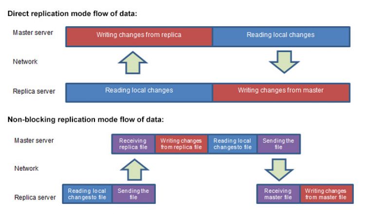
Version 2018T1 provides the possibility to speed up the replication process, by offering two modes of replication: direct and non-blocking modes. In normal network conditions, direct mode is the most effective. However, during replication local users have limited access to databases; they cannot write to databases while replication is either reading data from the local server, or writing to it. They also cannot read from databases while replication is writing data to the local server. If many changes need to be replicated, or if the network connection between the servers is slow or unstable, local users might not be able to access the COS server for some time.
In non-blocking mode, users are only blocked from using the server when data is being written to or read from a replication file at the local site, and users can continue working while files are being transferred between sites. As file operations are typically much faster than network operations, the downtime for users should be shorter in the non-blocking mode. However, the overall replication time might be longer as the two servers operate in sequence, and not simultaneously
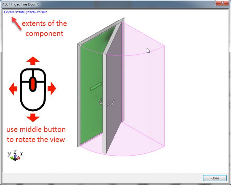
View the components and its limits
Information about the extents of objects in the browser window have been added. When inserting a component from the library to 3D model, for example, the use can view it in 3D and rotate it, and also see the extent values for the component.
Hull
Speed up the design of shell plates with copy and move functions.
Speed up the design of shell plates with copy and move functions.
Creating shell plates requires accuracy and precision in 3D. Version 2018T1 allows users to reduce the time used for routine work by using the copy or move functions for shell plates. The new shell plate is part of the active block, and the only restriction is a requirement for the origin plate to be related to symmetric hull lines.
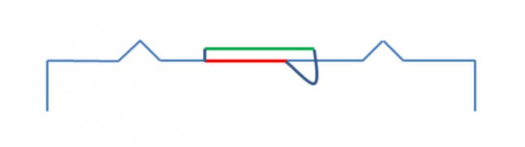
The updated “Template to sketch” feature uses the new template properties and results in additional information in the tables. The additional data includes angle information, step distance, and height for clear production output.
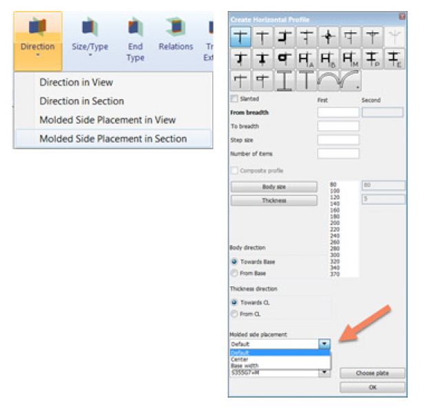
Composite profile
In 2018T1 production data can be created from single curved shell frames. The profile sketch inserts the face plate from the generated DXF file and displays it above the body
Profiles
Assemble information
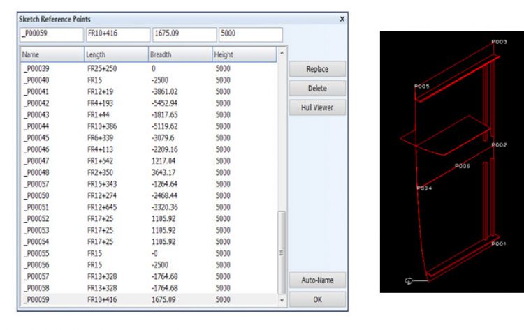
Measurement after assembly information is generated ensures the quality. With the new “Reference Points” feature, a list of checking points can be created that the system uses for display in the panel sketch. The points are stored in the CSV format to facilitate exchanges with external software. The user can grab these points from the view or Hull viewer. The points can be replaced or deleted.
Weld Management
The system manager can define the start and end symbols for weld lines. This helps engineers to see the weld lines more clearly in weld drawings
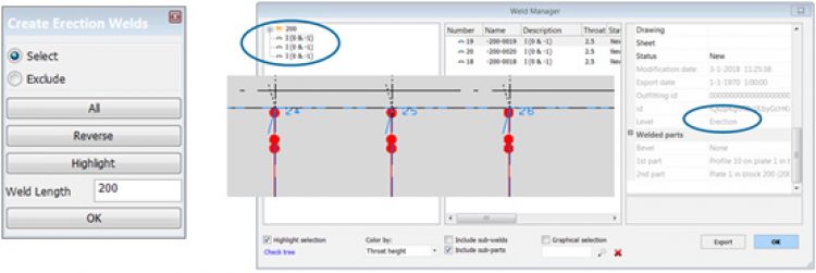
The so-called “Erection” welds help production staff to join blocks. This new feature splits a combination of profile weld lines from the selected end, with a given weld length distance. These relatively small weld lines are welded after the block is joined together. This is the reason why these weld lines get to the “Erection” level and can be found in the root of the Work Breakdown Structure.
A weld line will get a new “Block” join level when the weld line is related to two blocks. The weld line is assigned to the lower block in the block order of the Building block Overview list. These weld lines can be found in the root of the Work Breakdown Structure. The user interface of the “Building Block Overview” will be improved in a later version so that the system manager can reorganize the order in the list more easily.Weld Manager settings are now available in the system management settings, and all bevel and weld functions are documented and available for all users.
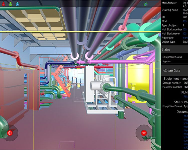
Information Management
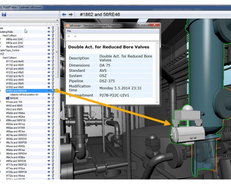
Collision detection directly in eBrowser – one step further in project management
In addition to efficient browsing of 3D models, comparison tools and storing discussions, it is now possible to check for collisions directly in eBrowser – with the new functionality in 2018T1 it is as easy as a few clicks. The collision detector inside eBrowser enables users to get a deeper insight into the 3D model and combine 3D models from different sources and check consistency between disciplines.
eBrowser collision detection
eBrowser collision detection
eBrowser collision detection
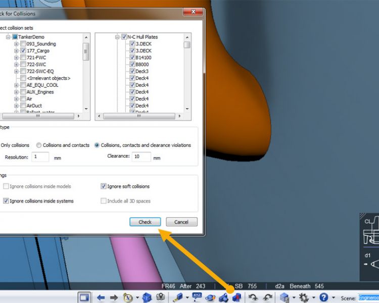
Right from the model tree the user can pick objects or tree nodes and quickly check if the selected objects collide with something else in the model. Additionally, a fully controlled collision test can be done from the main toolbar. Besides the precise selection of objects for the test, it allows the definition of clearance distances and the exclusion of soft collisions.
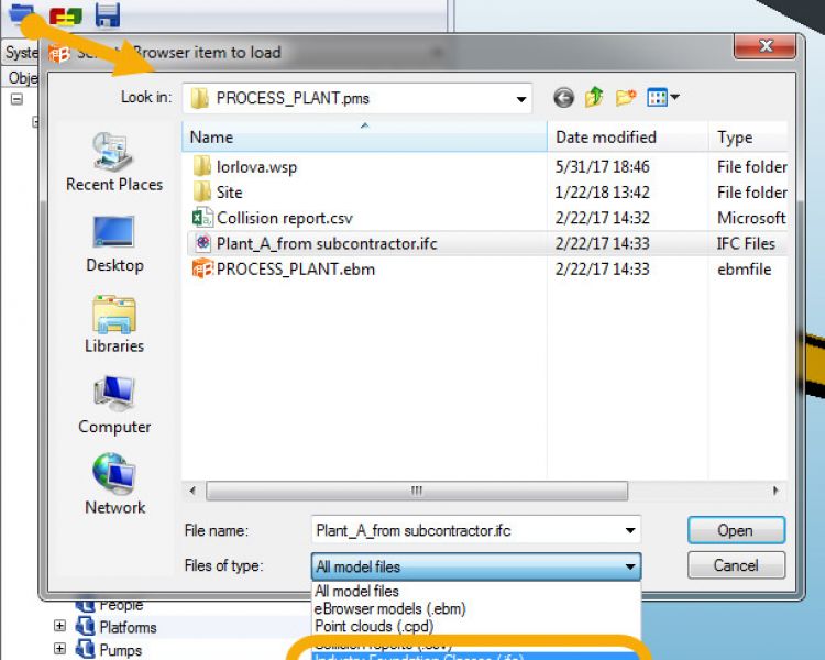
Import of IFC files to eBrowser models
To support projects shared among participants using different software packages, eBrowser allows the user to import IFC files. Collecting all 3D models in one place from various sources using IFC format opens up great possibilities for collaboration. Combining imported IFC files of project parts and clash check boosts eBrowser users in their quest for error-free design. The first time the IFC file is imported, it is converted to EBM format, to speed up later work.
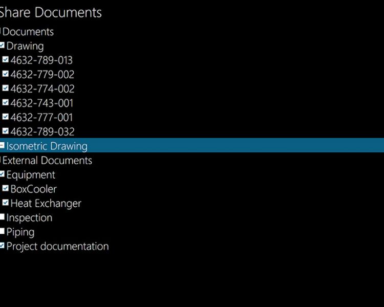
Download documents for mobile use on eGo
eGo
eGo
eGo

eGo
eGo
To go completely mobile users can now not only sync models to eGo from the eShare server but also download documents and use them offline. Documents can be used online, with the requirement of eGo being connected to eShare in real time, or selected documents or sets of documents can be downloaded to eGo and used on site. This applies to both PDF and DWG documents. Intelligent links from 2D to 3D are maintained, and the user can go from the document to the 3D model with one touch, including when the user is offline, and vice-versa when eGo can connect to eShare.
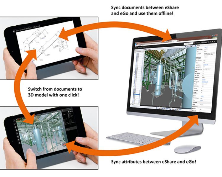
Besides documents, eGo shows attributes from eShare when online. This means that not only published attributes are visible, but also all kinds of additional data defined in eShare.
Additional improvements in eGo include a more intuitive Clip box and scalable annotation text.
eShare
User group permissions
In large projects where many users need to get information through eShare, it might be challenging to define who should have access to what data. In version 2018T1, it is possible to define groups of users and apply permissions for user access based on the group. For example, it is possible to create a separate group for installation crews and ensure their access only to the data sources that they really need in their work. This way you can not only limit access to sensitive data, but also offer targeted ways better to see only the data that different people need to see.
Categories auto refresh
In eShare users can use categorizations to color objects or build hierarchies. Previously, all possible categories needed to be defined by the admin before-hand, which was inconvenient in cases where the categories change constantly, such as when the hierarchy is used to show installation dates. To better support these situations, admin can configure eShare to show all categories instead of just the configured ones.