Release highlights 2017T3
Diagram
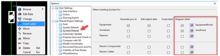
Labels: easier setup and efficient use
Version 2017T3 offers numerous additions for label handling: starting from improved performance when updating a large amount of new labels, to a better user interface for processing and formatting data in the Label Definition tool and Unicode support for the new 2D Symbol editor.
To comply with some Diagram styles, pipeline labels can as a default be parallel with the pipe run line segment where the line is picked.
For easy handling of changes, it is possible to change the pipeline of a Connector object
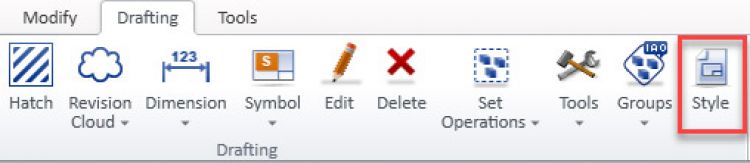
New option to define and reset Drafting Style for diagrams
The drafting style defines the basic settings for drawing annotation: text layers and size, lines styles and colors etc. In 2017T3 it is possible to define the style for Diagrams and apply it to produce a uniform look for all Diagrams in the project with a minimal need for administration.
Outfitting & Plant Design
User interface: Smart cursor, view cube and more additions to 3D navigation
In line with CADMATIC’s strategy of prioritizing experience, we have continued working towards adding new features to the 3D core. The next step after the new visualization has been the addition of new navigation options. Version 2017T3 offers users a smart cursor that prompts the user with hints relevant to the current situation or commands selected, and visually supports design work. The visualization of connection points provides information about the nearest connections and includes highlighting the flow direction in color. Views can be rotated with view cube (Ctrl + middle button click) on the fly.
Further improvements include the navigation command “Nearest Pipe Geometry Point”. It also snaps to the intersection of the main run and branch.
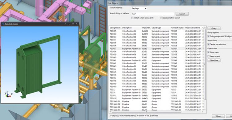
New Find objects tool
Finding something in 3D model can sometimes be tricky. The new “Find objects” tool allows the user to find anything from the 3D model based on a simple request. Key tags search for any unique identifier like Position Ids of model objects or names of model groups. Alternatively, it is possible to refine search criteria, searching for specific metadata. The objects found can be shown in a separate window and/or highlighted and centered in other views.
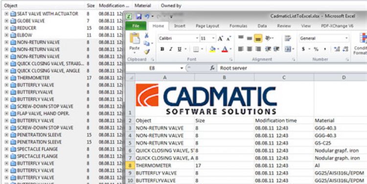
Fast Export to Microsoft Excel
Any listed item lists can be quickly exported to Microsoft Excel using the “Ctrl E” shortcut. The list can be anything – a found object matching any criteria, or list of drawings or components. Selecting one, all, or just some lines and hitting the shortcut creates an Excel list containing the selected rows. The feature is especially useful for the quick extraction of any data.
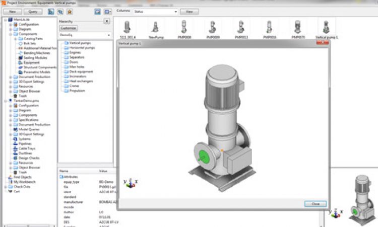
Shaded views also for thumbnails and previews
Since the introduction of new visualization core, we have strongly encouraged all users to benefit from 3D shaded views. In version 2017T3, we have added support for shaded views in the library thumbnails and preview windows. In the preview window node points and center of gravity for components are also shown with colored points
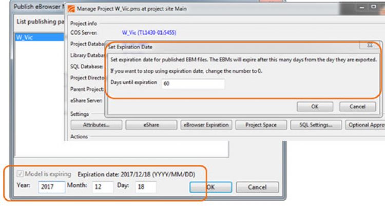
Taking protection of IPR to a new level: Predefined expiration date for eBrowser files
As an additional layer of security, a set validity date for eBrowser files has been introduced. Providing access to see and walk around the 3D during the design and building phases might be essential. However leaving the indefinite 3D model that potentially can be used as a sketch for next projects is often seen as a needed limitation by the owners of the design.
Expiration dates for eBrowser files provide the possibility to control access to the design solutions after the completion of the project and ensures that outdated files are not used.
The project-level administrator can add a general setting for expiration days as a default. While publishing, the expiration date can be adjusted as needed.
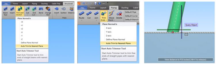
Auto trimmer tool for beam and pipe ends
The possibility to trim or stretch beams and pipes to the nearest plane provides users with a useful tool to make cuts of beams or pipes based on existing planes. The cutting planes can be hull structures or stiffeners, structural component plates, and in general any planar surfaces of components in the 3D model. It is easy to adjust the legs of supports or foundations on sloping decks or floors using this command.
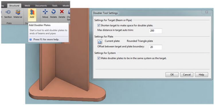
Automatic doubler plates for beams
Adding doubler plates to beam ends is now a simple task: the user picks the plate type from the library and then just inserts doubler plates by selecting a beam end and accepting the insertion. The Doubler tool can also be used in more complicated cases where beam is not perpendicular to the nearest plane, as with the Auto Trimmer.
Perspective view (pan and move)
Support Designer
Support Designer tool can be now started the Support Tool from new ribbon entry. There is now a possibility to use the tool without a Location Plan. This way user can save time while working mostly with one or a few Location Plans.
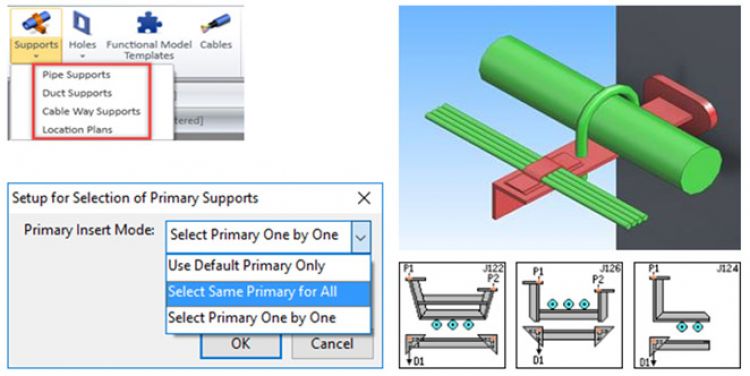
It is possible to use multi-clamps as primary supports alone or together with regular primary supports. These can be used with all different support wizard templates. Additionally, support drawing generation is updated to handle multi-clamps. There are seven new support wizard templates type J122 to J128. Support drawing generation is updated to do automated labeling of unique end cuts of these new templates. Now also for wizard supports the user can choose if he wants to select types of primary supports one by one or use for example U-bolt primary support for every pipe in one support or without any questions to use the default primary support from the piping specification of each pipe.
Doubler and AutoTrimmer tools are added for easy access to facilitate handling of profiles and plates. Template configurations support now cx export/import, and thus the referenced parts that exist in the project and templates will be valid when a new project created under the same library or to new COS server.
General additions
Hidden line removal in 2017T3 optimized for big imported component models. Hidden line removal process is much faster for such views which show complex imported components.
Possibility to set additional parameter for the bending machine. Named dimension attribute BndPln_z for Bending Machines to defines the distance to the floor and enable checking of collisions to the floor. Additionally, the option to attach geometric model of bending machine to bending machine definition was added.
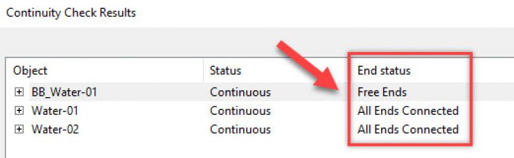
Pipeline continuity check improved to find and get information about mismatching connections at the ends of a pipeline.
Hull
General
Hidden line removal in 2017T3 optimized for big imported component models. Hidden line removal process is much faster for such views which show complex imported components.
Possibility to set additional parameter for the bending machine. Named dimension attribute BndPln_z for Bending Machines to defines the distance to the floor and enable checking of collisions to the floor. Additionally, the option to attach geometric model of bending machine to bending machine definition was added.
Pipeline continuity check improved to find and get information about mismatching connections at the ends of a pipeline.
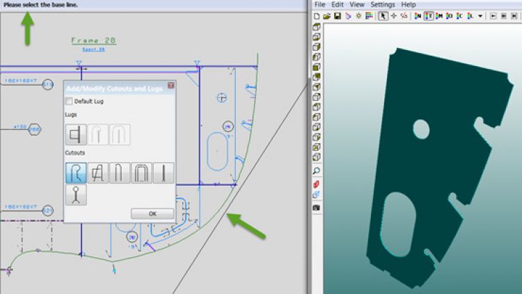
When a cutout requires an extra opening to assemble a part on a curved jig plane, the jig baseline is presented automatically when inserting or modifying cutouts, so that the cutout openings can utilize the jig baseline.
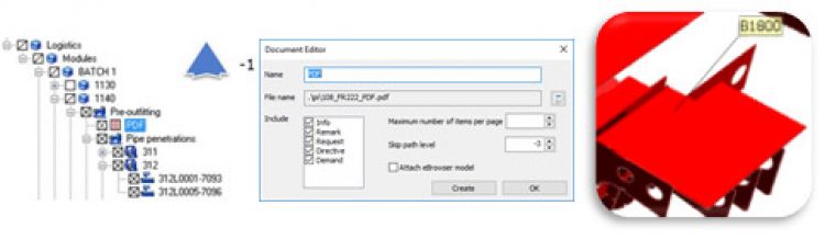
The PDF information created by the document tags in the work breakdown tree of the Hull viewer has been improved. The item report and label presentation have been optimized.
Bevel and Welds
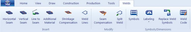
The seam and weld functions have been moved to the Welds ribbon tab.
Bevel and weld lines are now applicable for all construction types and the presentation of weld lines and bevel models has been improved in drawings and the Hull viewer.
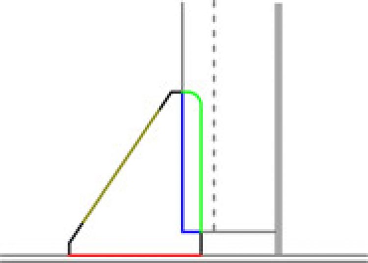
The bevel and weld line definition for brackets has been simplified. The exact position of the weld lines is generated automatically, according to the contour and overlapping/connecting construction.
Weld lines can be used to control the welding process. A partly rejected weld line can be split into two or three parts. To trace these changes, the user can lock the original weld line so that it remains in the weld database after splitting.
In some cases, a weld line is not created automatically by the system, for instance, between two overlapping plates, or crossing pillars. With the “Insert weld line” feature, the user is able to insert these weld lines manually by selecting the overlapping items and defining the weld properties. The weld line is then connected to these construction parts.

The Point feature in the Hull viewer assists the user to define x, y and z values in all Hull input panels. This is a useful feature to define special positions or perpendicular view planes where manual weld lines should be added.
Shell application developments
The orientation text “To Hull”, which can be displayed on shell plate production data, has been replaced with two separate text items “SB” or “PS”. The system automatically selects the correct indication depending on the position of the shell plate production data.
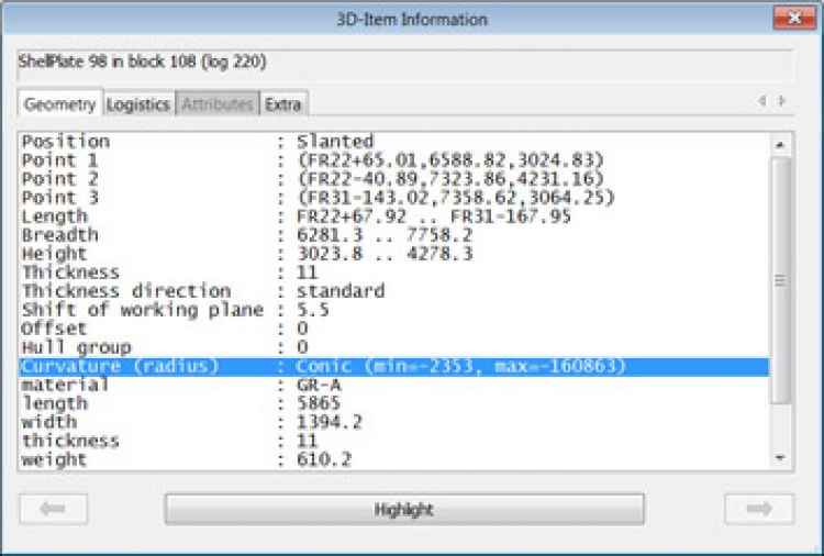
A new entry has been added to item information for shell plates. The entry is called “Curvature” and displays an approximation of the shell plate shape, followed by the curvature values (expressed as a radius in mm). The estimation is based on a user setting that defines a particular radius for a surface to be considered flat.
There are four possible results for the approximate shape:
- “Flat”: this is shown when both values are close to 0; the shape is approximately planar.
- “Conic”: this is shown when one value is close to 0, but the other is not; the shape is similar to a cylinder or a cone in the areas of greatest curvature.
- “Elliptic paraboloid”: this is shown when neither value is close to 0; the shape is similar to a spheroid in the areas of greatest curvature.
- “Hyperbolic paraboloid”: this is shown when neither value is close to 0 and the values have opposite signs; the shape is similar to a saddle in the areas of greatest curvature.
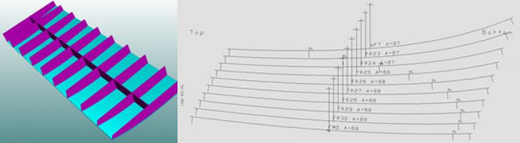
The roller line is marked when a plate is considered to be “Conic”. The roller is marked as a straight line when line heating is used, while it can be curved for cold bending.
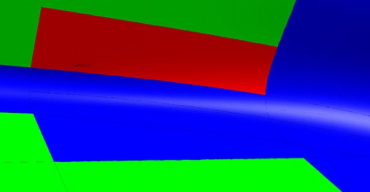
Each approximate shape is assigned a process and job number that can be used to divide the shapes between your deforming tools. By using the logical color filtering in Hull viewer all four plate types are assigned separate colors.
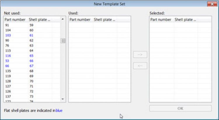
The “Curvature” definition assists users to indicate flat plates in a block so that the user can prevent the creation of a template set in special cases. There is no need to make a “template set” for a shell plate when the plate is flat. With the same interface the user can define pin jigs and some flat shell plates. To give the flat plates the indicative color (flat) the user can create the “template set” when it is still needed (because a flat plate can still be slightly curved, depending on settings).
The “Curvature” definition assists users to indicate flat plates in a block so that the user can prevent the creation of a template set in special cases. There is no need to make a “template set” for a shell plate when the plate is flat. With the same interface the user can define pin jigs and some flat shell plates. To give the flat plates the indicative color (flat) the user can create the “template set” when it is still needed (because a flat plate can still be slightly curved, depending on settings).
Extra lengths for shell plates can be inserted and modified easily.
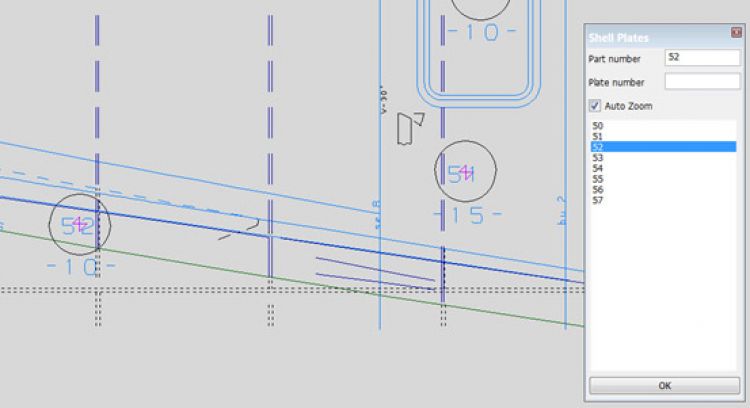
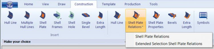
An “Extended shell plate relations” feature has been added to the shell plate modification function. It helps the user to find the shell plate more easily in shell views. This is a particularly useful feature when many shell plates are present in a shell view.
The updating process of Hull lines after recalculation has been improved by speeding up the total recalculation feature.
Shell plates created with pre-2016T3 versions can be imported with the new import function. The system uses the old input data and translates this information for the new method. The import tool assists the user to check the presence of used hull lines and hull shape groups. It results in a shell plate definition identical to that created for a new shell plate. The template data is not imported.
Production reference lines are automatically marked on shell plate production data. As such, it is no longer necessary to use hull lines for these reference lines.
Template descriptions can be printed on shell plates even if a construction part has the same location.
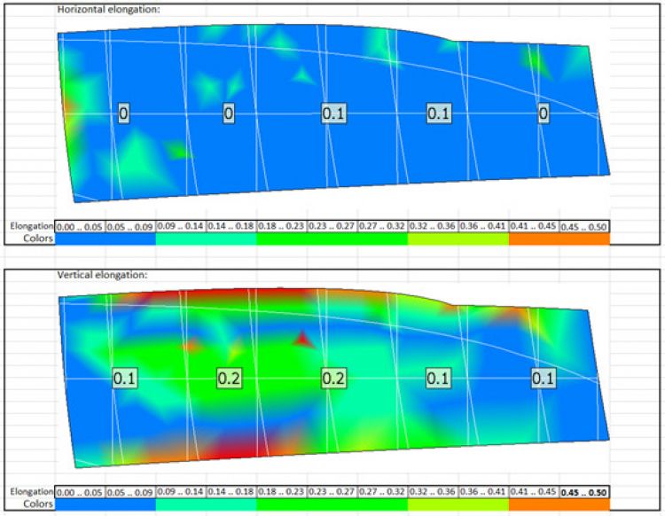
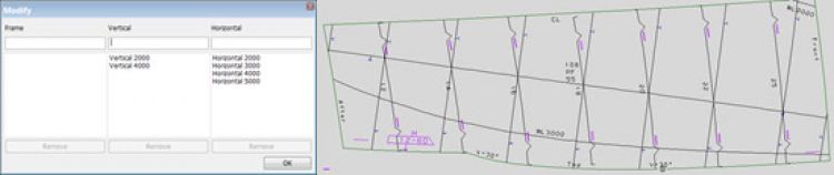
The maximum extremum elongation is now available and can be displayed in the elongation list. The maximum extremum can be used to define the maximum color range, so that the elongation report has more value for production. The marking lines are displayed in the elongation picture, which makes it easier for production to indicate different elongation areas.
Shell plates and knuckle plates are displayed in hidden line removal drawings, so-called ISO drawings, which are created in the 3Dshow application.
Composite profiles
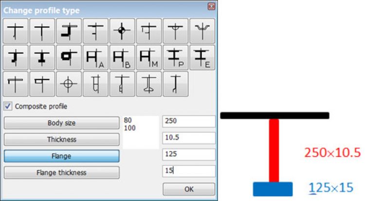
A new option is available for profile creation and modifying that allows the user to code bodies and flanges separately in the production phase. The design system treats the profile as a single entity, while it produces the body and flange as single parts with their own production ID names. This feature is available for straight profiles and pillars and is restricted to some profile types. In order to make the parts unique, the prefix or postfix can be chosen in the system management application. The creation of production data for single curved shell frames is still under development.
Pillar to Profile
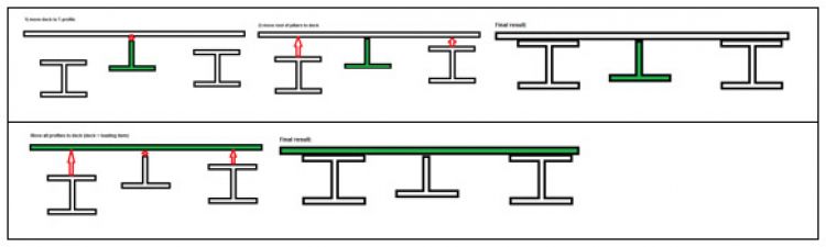
A new feature has been introduced that allows engineers to connect the baseline of a pillar to a plate, thereby changing the pillar into a profile or a pillar-profile. This new feature has great value when the engineer wants to create a construction based on beams and insert the plates later. The Plate and Pillar position can be aligned depending on the user preference.
Assembly information
Measurement features have been extended to ease the assembly process even more. In previous versions, angle markings were implemented for shell frames and profiles. In this version, this has been extended: the connection angle between two parts is now marked near the marking line. This is especially helpful when assembling plates on a shell plate panel which is located on a pin jig.
To join plates in the correct position, with consideration for weld openings, extra marking lines have been added including the distance to the edge minus the used opening. Production can use this information to check a distance of 200 mm between plates before and after welding.
PDF as standard Output
A standard Hull PDF plot driver has been implemented that can be used to create a PDF from drawings and sketches. PDF files can be created at the same time that DXF files are created from drawings. These PDF files can be used in eShare and contain searchable text.
Information Management
eBrowser, eGo, eShare: Measure can snap to imported objects
eBrowser’s measure is now able to snap to objects that are represented as a collection of triangles (mesh objects, or polygon sets in CADMATIC terminology). This is especially helpful with imported objects which cannot often be fully represented as native CADMATIC primitives, but it should also be helpful with some CADMATIC originating objects, like cut cable trays, some air ducts, and bent beams. The mechanism will try to find sharp edges from the objects, and allows users to snap to those. Also all points in those models can be snapped to.
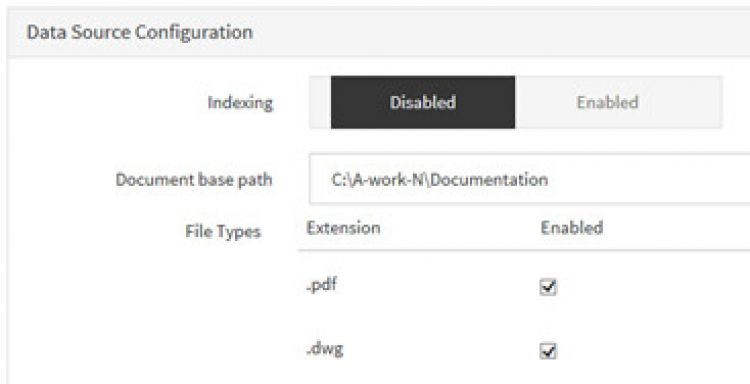
eShare: DWG file support
In version 2017T3 eShare can use DWG files in all document data sources. When opening DWG files they are converted to PDFs on-the-fly, and functionality previously available for PDFs, like injecting links, is also available for DWGs. This is especially helpful for customers who have DWG drawings with AutoCAD fonts, as now it is no longer necessary to do special tricks to make link injection work.
eShare: Faster way to update large number of object or group statuses
Previously updating object and especially group statuses required a substantial number of clicks. In version 2017T3 updating of statuses has been brought directly to the attribute pane and group status can be updated via examining the group members. The changed status is immediately visualized in the 3D view, which makes the effect of the status change more visible to the user. These improvements allow much faster entering of group statuses. To view more easily status changes made by other users, there is now also a button for refreshing the selected visual style in the 3D view.
eShare: More flexible possibilities to do integrations with the out-of-the-box adapters
CMIS adapter and Excel adapter receive a substantial number of new features in version 2017T3, supporting customers who want to use the standard out-of-the-box integration functionalities in eShare.
Excel adapter supports filtering rows by revision, allows using regular expressions for filters, and it also supports defining ranges for the values that are received from the Excel. Ranges are supported for strings, numbers, and dates. Date ranges can be relative to the date when they are viewed. These improvements allow easier integration of a growing number of different kinds of Excel files, without the need for any custom development. With value ranges being supported, also files with a large number of different values, like dates, can be visualized in a way that is more efficient for the user.
CMIS adapter allows administrator to define a base path to reveal only part of the document repository to the users. Administrator can also define filtering based on document attributes, which allows for example viewing only documents that are approved or released. This way document repositories that contain engineering documents but also more sensitive information such as offers or financial documents can be integrated to the 3D model. This also allows repositories that contain documents for several projects to be used, so that only relevant documents are shown in each project.
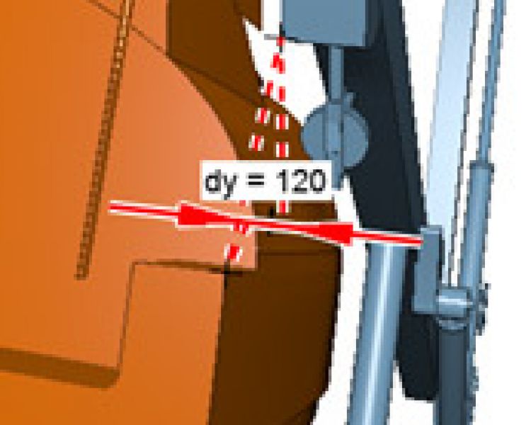
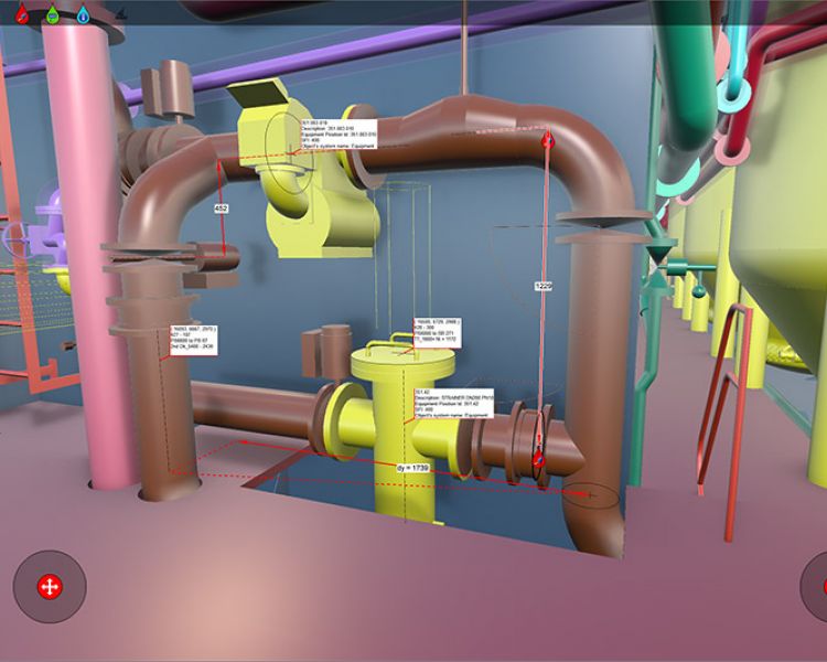
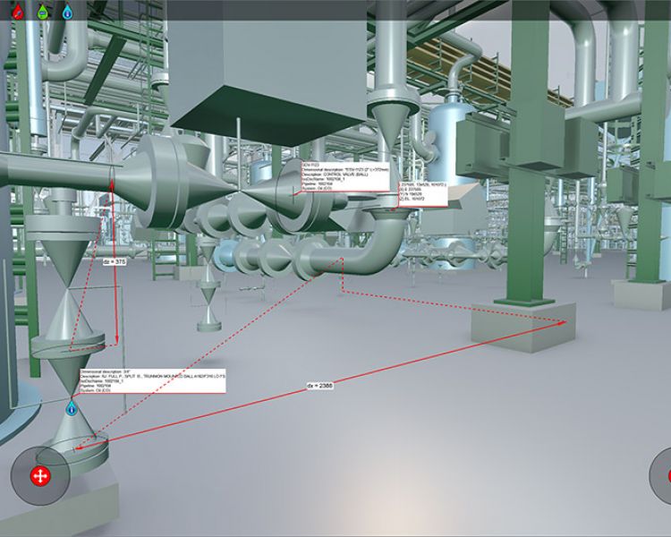
eGo: possibility to annotate 3D view with labels
In addition to adding measurements to a view, in version 2017T3 it is possible to add labels with suitable object attributes or coordinate values. This allows users to utilize the 3D model more efficiently for example at a construction site by making the necessary measurements visible on top of the 3D model to support for example installation work.
More additions for navigation in the model and visualization
To get even more precise navigation, the user can drag an orbiting point to any location and then rotate the 3D view around that point. A button in the main toolbar restores the previous camera location if the user wants to go back to a previous view.
Additions to settings allow selecting which 3D space to use for the map generation and specifying virtual joystick alignment.
If eGo is connected to an eShare project, synchronizing the model downloads offline copies of visual styles defined in eShare to the tablet, which allows users to color the model based on the visual styles. This is especially helpful if user needs to go to the construction site to verify or update information that can efficiently be visualized with colors, such as construction or verification status.
eGo annotation of 3D view
eGo annotation of 3D view
eGo annotation of 3D view
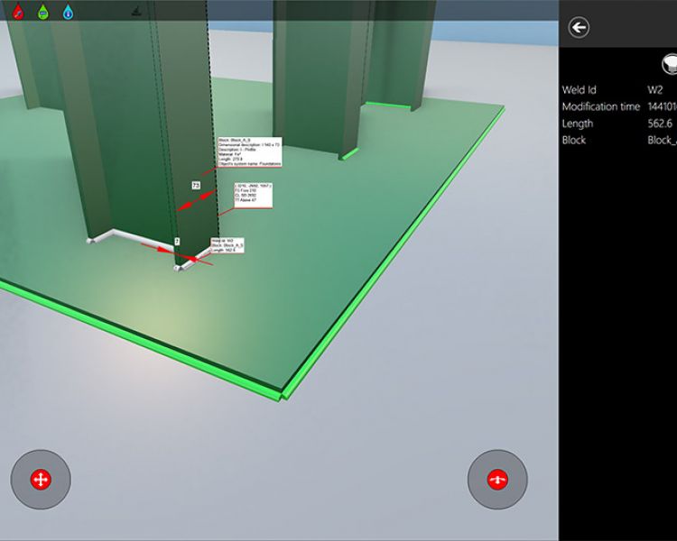
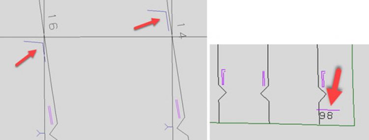
eGo welds