Release highlights 2017T2
Diagram
New Label definition for Diagrams
In support of our strategy of prioritizing user experience, an important step has been taken to simplify Diagram administration. It is now significantly easier for administrators to create, maintain and update labels –no script coding is needed!
The Label definition window is very similar to other labels in 3D applications. Data requests are created directly from the table structure in the SQL database (diagram-specific feature). Old style labels are still available for customers who prefer keeping the existing label definitions in their projects. A combination of old labels made with scripts and new labels made with the interactive tool can be used in the same diagram. If diagrams use the new label definition it is faster to update all labels. Labels can be inserted via the Select Label window that can be added to the Ribbon.
New 2D Symbol Editor available for Diagram symbols
The new 2D Symbol editor can be used for all Cadmatic Outfitting applications with 2D symbols that are symbol-editor compatible. This is especially useful for diagram administrators when creating new symbols for object templates.
The symbol editor includes new drafting functionalities like undo/redo, cut, extend, snap to end, middle, near, etc. For diagram symbols, the 2D symbol editor has a diagram-specific functionality to add connection nodes.
Outfitting & Plant Design
2D Symbol Editor
An interactive 2D Symbol Editor with standard 2D drafting is available for creating and editing 2D Symbols used in drawings. Previously, this tool was used only for Drawings to allow final makeup in 2D. The tool provides a standard 2D functionality for making geometries and tools such as trim and extend, offset, fillet and work with layers.
Additions to automatic labeling
Automatic labeling is now faster and includes the possibility to label very small objects in the views. Even the smallest objects in the view (like Cable Router node points) can be automatically labeled.
Additional types of labels enable the labeling of the first and last spools of the pipeline on a drawing.
Interactive Component Modeller
The Undo/redo command has been added to make the process of creating 3D components similar to the 3D modeling process of the design model.
It is possible now to remove unused points inside the GDL components.
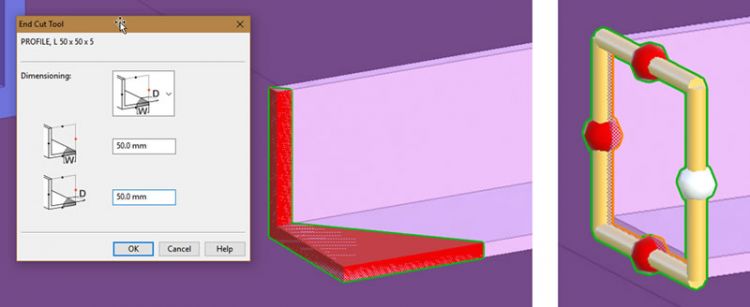
Planar end cuts for beams
Beam ends, can be cut with one or more planes. The tool visualizes cut planes and user can input the values for the cut parameters or drag the points in 3D and adjust the values. The existing end cuts can be copied to other beams.
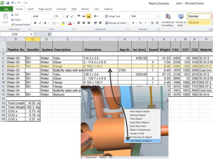
ExcelExportPlus tool now available with add-on installer
The Cadmatic Excel Report Generator, previously available as a separate tool, is now included in the installer with other add-on. It generates various reports directly in Microsoft Excel format without using ICGD format controls. Templates and reports like material lists, cutting lists, etc. are defined via a user-friendly interface and a wide variety of settings that are stored for each report type. In addition to different types of 3D model data and attributes, it is possible to include COS-specific properties in the reports.
The Excel Report Generator Outfitting includes an embedded link to eBrowser. By simply clicking lines in the report the 3D objects are shown on the fly in eBrowser. It also works vice-versa: clicking on 3D objects in eBrowser highlights the corresponding objects in the report.
Hull
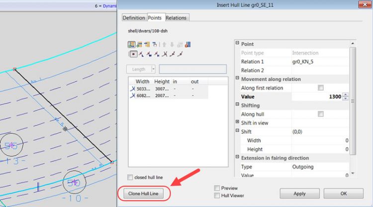
Copy Hull line input
It is now possible to insert a new Hull line by using the input from an existing Hull line with the new “Clone Hull Line” function. It is possible to use the same relations, properties or insert new points. The “Shift” and “Move along relation” properties help the user to move the Hull line to a new position.
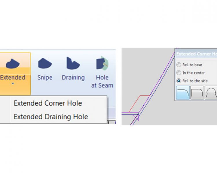
Corner and draining holes
Users have strongly requested the ability to make corner and draining holes topologic. In older versions it was possible to create relations where the holes became part of the plate contour. It was a time-consuming task to create these relations (see example below).
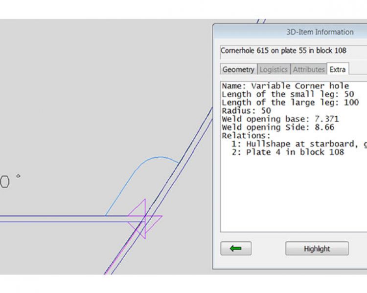
With the new “Extended Corner Hole” and “Extended Draining Hole” functions it is much easier to create these holes and ensure that they have topological relations.
Plates with holes can be copied and, if the system finds new relations, it uses them. When the contour relations are beveled, the hole can use the bevel opening to enlarge the opening. The bevel opening is automatically adjusted when the bevel or plate thickness is changed. This helps the welder to weld small edges even if the distance is small.
Corner and draining holes
Corner and draining holes
Corner and draining holes
Shell plates
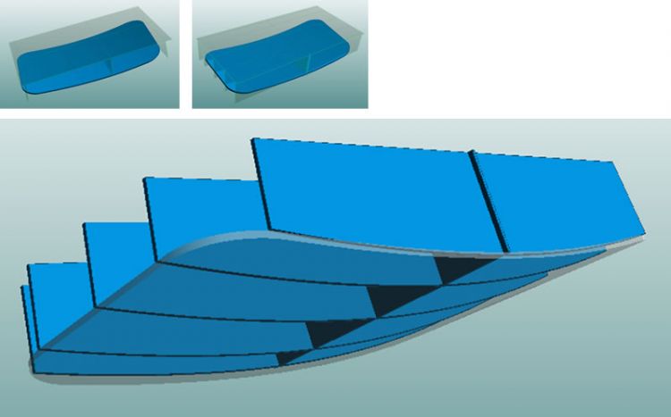
Extra length
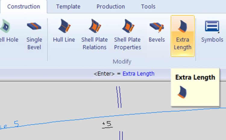
The Extra Length function for shell plates has been implemented to provide shell plate borders that can be extended as with flat plates. Hidden line drawings can be created from shell plates with the Work Break Down sketches and 3D Show functions.
Templates
In most cases, the Sight line plane needs to be calculated in the longitudinal direction of the plate. However, in some cases it is better to do it in the latitudinal direction. The Template wizard now uses the grid direction to define the best Sight line plane. The method that does not influence the Sight line plane position can be chosen.
Bevels and welds
In version 2017T2 the bevel and weld functions have been extended to include more construction types to which bevels and welds are manually or automatically assigned. These construction types include brackets and face plates. This information is available in all output forms like drawings, sketches, and DXF.

Hull Viewer
The Hull Viewer is a handy tool to inspect the model during the engineering process and its assists engineers to select items for modifications and reports. With the new Point hot key the engineer can use the * point as input in any Hull input panel.
Recalculate items
The CRC-check prevents unwanted recalculation during the engineering process. This check was implemented in the past to speed up the Hull server. When a system manager modifies defaults in norms that change particular construction items, all the data is recalculated. Only the affected construction items, however, actually require recalculation. To avoid the time-consuming recalculation of all items, the “Recalculate 3D-items” function has an “Update unchanged 3D models” command with which users can select a construction and force the Hull server to recalculate.
Information Management
Store discussions about projects with markups in eShare
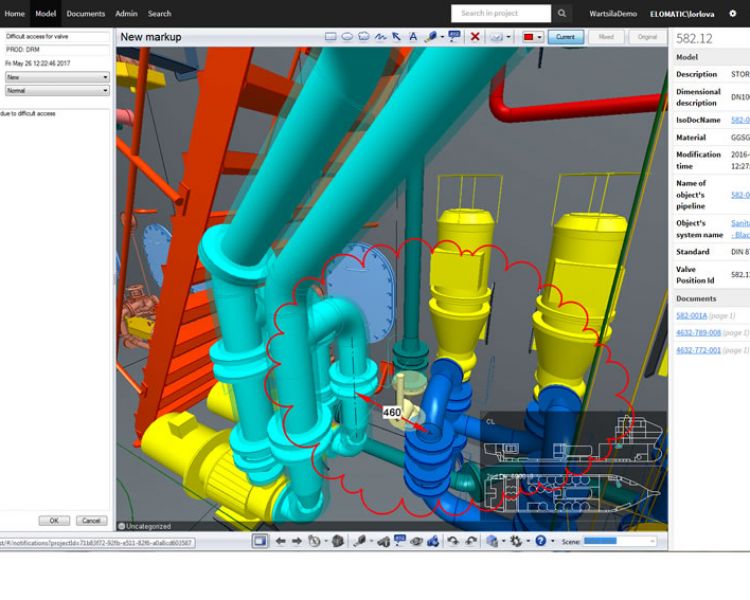
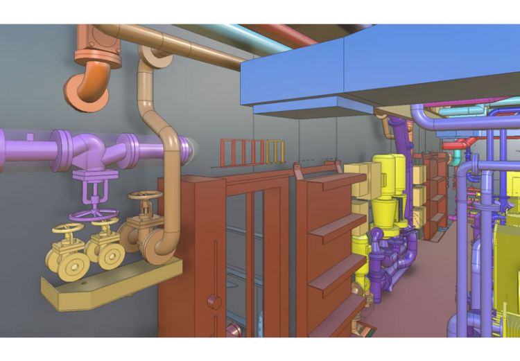
The collaboration process between designers, building sites, subcontractors and owners often involves discussions related to the 3D model that can be facilitated with markups in eShare. Browsing in 3D has many advantages – it is possible to literally walk around the project and check any detail. Adding markups on top of the 3D model allows users to communicate their thoughts or insights with other project parties. Project review and management meeting memos can be stored right on top of the 3D model where others can access it immediately.
2017T2 eBrowser
2017T2 eShare
2017T2 eShare
2017T2 eShare markups
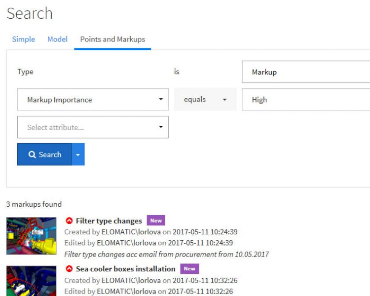
2017T2 eShare markups list
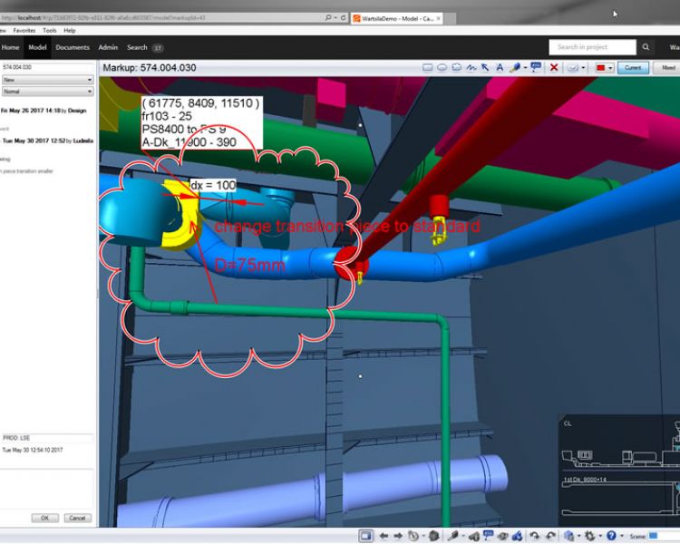
Any eShare user can add markups to the model, indicate with clouds or arrows what the subject is, add coordinates and text and write explanatory notes. Once saved, the markup can be seen by other eShare users on the project. Additional comments and priority levels can be added. If changes were made to the model, it is possible to compare the changes with the markup that requested the changes.
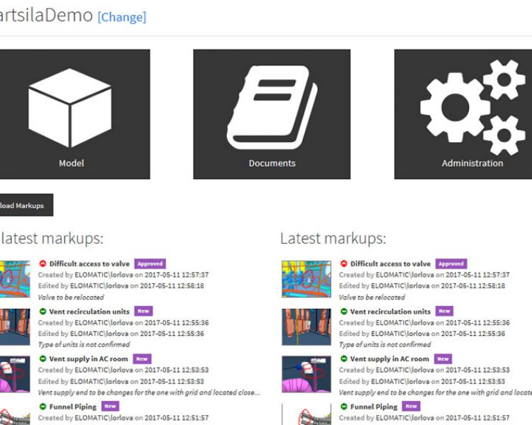
The latest markups in the project and those made by the user are displayed on the eShare home screen. It is possible to import markups from eBrowser of the same model or from another eShare environment. As such, markups from subcontractors and other contributors can be added or updated to the server. If an existing markup is modified, only the modifications are added to and synced with the server.
The search mechanism provides the possibility to list all or only certain types of markups as well as export them to Excel lists or *.ebx markup files to load by eBrowser users.
eBrowser: New visualization core
In the previous version customers could try out the new eBrowser visualization core in a public beta version. Now that all testing has been completed and feedback received and implemented, an eBrowser 64bit version with the new visualization is available (also for the light version). Besides visual improvements, it optimizes performance for large 3D models and improves the user experience.
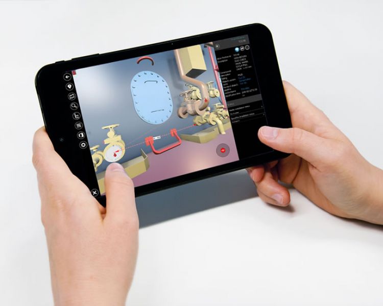
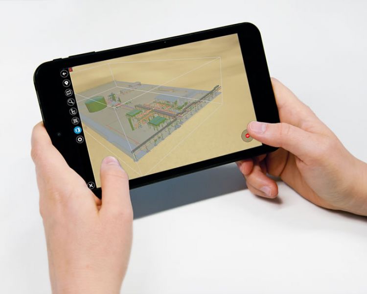
eGo: New visualization core and enhanced control over visualization
A completely new 3D visualization core that provides better 3D graphics and improved performance has been implemented. The visualization settings can be adjusted in the Model Settings view. More possibilities to hide or make objects or groups transparent in 3D make it easier to see the necessary parts.
2017T2 eGo
2017T2 eGo
2017T2 eGo
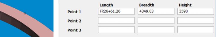
eGo: Measure distances between points
Dragging two measurement icons from the top-left corner of the 3D view on top of 3D objects creates a new measurement line; measurement lines can be removed by dragging them back to the icon. A measurement point snaps primarily to the nearest edge, centerline or sharp corner, but if the object has no snap points, it snaps to the nearest surface or edge. The measurement settings can be adjusted in the Model Settings view.