Harnessing the knowledge of specialists in CAD/CAM software - Case: Shell plate development
Posted on March 16, 2020
Only a few decades ago, the use of various specialists in the engineering and design of ships was commonplace. Today, it seems that specialists are disappearing and that the younger generation expects software to solve engineering challenges. CADMATIC software development has provided assistance by harnessing the knowledge of specialists. This article will demonstrate this with the use of a highly specialized area of shipbuilding – shell plate development, which for decades relied on human knowledge and experience.
Before looking at how CADMATIC software has harnessed specialists’ know-how for shell plate development, it is instructive to review the history of shell plate development and related software development.
History of shell plate calculation and related software development
The calculation of shell plates with consideration for plate stretch was unknown to many in the 1980s, while it had been determined manually by specialists at shipyards in the Netherlands for many years already.
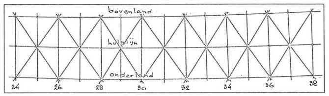
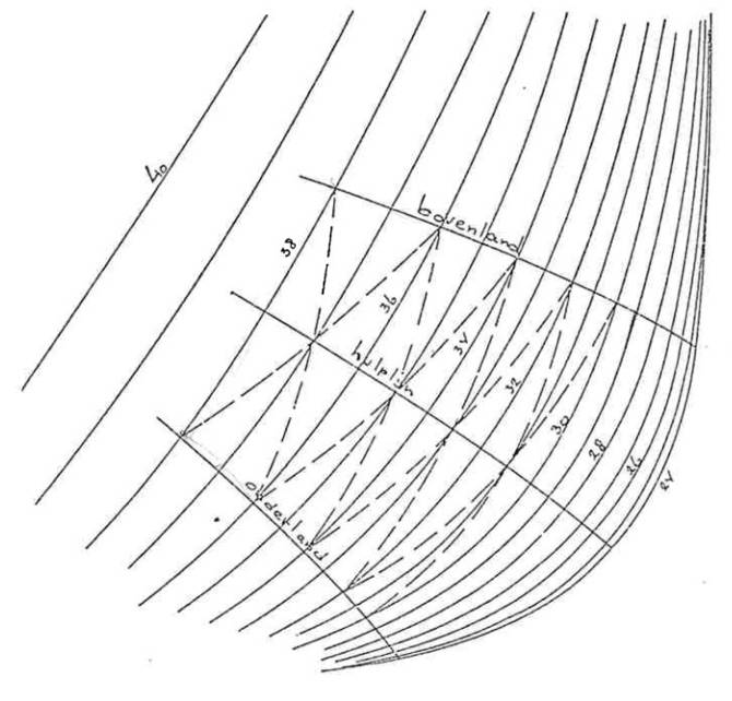
The so-called spear method and cross table were very common at the time.
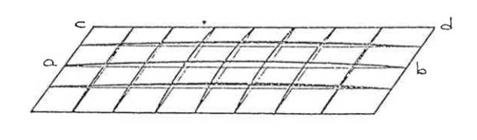
The data was extracted from a mould loft and, in most cases, directly projected onto a steel plate.
The difference between real lengths in 3D shells and the 2D expansion was the stretch, which was determined by specialists.
Two types of plates were involved in this process: plates with side stretch and plates with centre stretch.
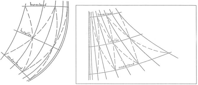
The specialists decided which type to use in order to choose the correct expansion method.
In the 1980s, this manual process was translated into a computer program, which used the shape of the ship as the input. The ship’s shape was then only presented as a 3D wireframe model that included frames, waterlines, verticals and knuckle lines.
The advantage of this method was that it was based on many years of experience. The use of the software was limited to specific specialists who could understand and interpret the results to correctly fit shell plates, including elongation tables. The position of seams and butts significantly influenced the result and limited the possibilities. Fortunately, it also gave the specialist the flexibility to come close to the desired result.
In the Netherlands, the production method for deforming shell plates was based on the above-mentioned data. The big advantage was that shell plates, in most cases, could be processed without extra length. For many shipbuilders in other countries, this was incomprehensible. A combination of specialization areas was required and often achieved after many years in the field.
In recent years, the assembly process has been increasingly optimized and vessels have also become aesthetically more attractive, which has resulted in much more complex shapes. The variation in ships has also increased considerably. Besides commercial ships, beautifully shaped luxury yachts have become popular. These shapes are nowadays created as shaped surfaces instead of wireframe models. Shipyards also require shell plates to be aligned with construction and, therefore, to be less affected by the deformation process. There is also a drive to minimize the number of welding meters, which creates tension with the amount of deformation time in production.
All of these factors have led to more pressure on this specialization area. In addition, as the younger generation were not motivated to learn these techniques, a new approach was developed to calculate and create shell plates.
The new approach was based on creating a software program that could harness the expertise of specialists, thereby reducing reliance on such specialists and freeing designers to focus on design, while the software did complicated shell plate calculations.
Considerations and requirements
The new approach of shell plate creation and calculation has already been on the market for some time and is mature enough to be accepted by specialists. The flexibility of this new solution as well as the supporting data is increasingly appreciated.
But what were the considerations and what inputs were valuable when creating this completely new method?
The basis for a curved surface is the shape. Ship design software packages such as NAPA, SARC, and MAXSURF. are commonly used to determine the shape. These shapes also come from more general software packages like Rhinoceros. This means that the solution had to be able to process all this information. In other words, an open structure was required to import any random surface data and translate it into a form that could ultimately deliver the right production data.
The position of seams and butts had to take the inner construction into account, but also be the basis for determining the shell plate contour. A high level of flexibility was required: relations needed to be created not only between shell plates, but also between shell plates and inner constructions. These topological relations had to support mathematical actions so the maximum plate dimensions could be approximated. Consider, for example, comparing distances of a measured shape.
It is crucial that the tool is flexible and simple, and matches today’s technologies. The tool should also provide insights into how welds are projected on the shape. This way, the insight of the specialist is translated into the tool. This so-called “what you see is what you get” assists young designers to understand what the result is or will be.
The definition of shell plates had to be disconnected from the production process, so that engineers have the freedom to use their creativity and are not limited by the production tool. In short, the tool should define what the shell plate looks like.
The weights, COGs and sizes determined during shell plate definition are essential in this phase of the engineering process. The construction can be topologically related to the shell plates so that weld and bevel information can be automatically determined. The width of a plate had to be determined by the bevel opening so that the specialist insight was no longer the responsibility of the engineer and did not require manual calculation. Details such as knuckle lines that do not lie exactly at the edge of a surface branch, had to be automatically solved by the system.
Production: Two methods of producing shell plates
Once shell plates are defined they need to be produced. The production method and processes, on the other hand, create a set of demands on calculation software outputs.
Production can be divided into two parts: engineering and deformation. For engineering, it is essential to determine whether shell plates can be produced or not. For deformation, the deformation parameters are most relevant and serve as input for the tools used.
The assembly process also influences the data that is projected on the shell plate. It is important that this information corresponds with the inner construction. There is no longer a distinction between inner construction and the shell, which creates equality and therefore means that the specialization is no longer needed, especially during the engineering process.
In order to produce a complex-shaped hull panel, there are two commonly available production systems:
* Line heating; based on the combination of bending and shrinking
* Cold forming; based on the combination of stretching and bending.
Line heating involves heating up spots/lines on the panel and quenching the same spot/line with cold water. This system is commonly used in Asian countries. The disadvantage is that it is very laborious, requires 5-10 years training to acquire the skill and risks the formation of martensite. Although line heating is still allowed according the 47th IACS Shipbuilding and repair quality standard, operators have felt the need to speed up the slow process and raise temperatures above the maximum temperature, accepting the risks of forming martensite, which makes the material brittle.
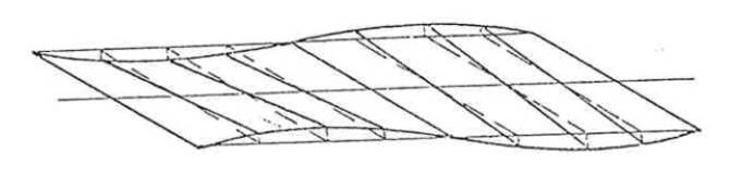
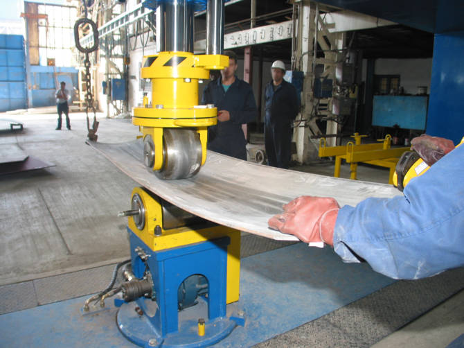
Cold forming is based on bending and stretching areas on the hull panel, thereby shaping the panel.
Stretching is achieved with a set of two small, rotating rollers. Stretching with a set of rollers is, on average, eight times faster and also easier to use than the line heating process.
The stretching lines are located in those areas that are typically not addressed during line heating. Hence, these technologies are called “reverse technologies”.
Stretching by rolling is the future
Stretching can also be achieved with the use of pressing tools for “stamping” However, these tools are not as effective as rolling tools. In addition, marks are created on the inside of the panel. This motivated Nieland to innovate the rolling process to an even higher standard which has led to encouraging results.
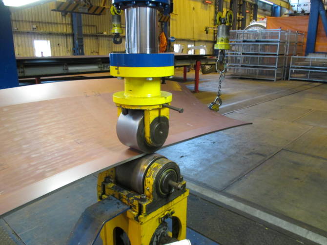
Picture of IHC Metalix rolling press
Rolling with a new design smaller roller in a transverse direction produces both longitudinal and frame shapes and makes stamping nearly superfluous.
The surface of the plate must be affected as little as possible. Stretching the plate only longitudinally, limits the efficiency of the forming process. The Dutch company Nieland, a specialist in cold forming technology, acknowledges this and has offered a solution for stretching plates both longitudinally and transversely for quite a while now with the use of an upper roller with reduced tread.
This method stretches the plate over its complete length, ensuring that the material surface is minimally affected and maintains its smooth appearance. Tests show that when the plate is stretched, it automatically takes on the correct form. The roller press can be equipped for rolling in both directions. Correct and clear stretch data is necessary to support this process.
This cold forming method has significant advantages compared to line heating. With cold forming the material properties are minimally affected, while line heating has a high risk of causing excessive damage. This cold forming process is also an average 8 times faster and there is no need for excess material; the first cut including bevelling can be the final cut because the process is very predictable.
CADMATIC tools
The afore-mentioned considerations and requirements for shell plate development guided the development of the CADMATIC tools that are currently available for the purpose.
For every phase, user-friendly tools have been developed so that the user needs minimum training. The tools all graphically represent what is happening or what will happen, which lowers the knowledge threshold. All data can be changed with the same tools, which makes input and/or adjustments ambiguous. Data can be copied or re-used and input properties can simply and efficiently be adapted due to multiple selections. Search functions have been added to find items quickly, a big advantage when work is being taken over from a colleague or when multiple engineers work in parallel.

The functions within the tools are well-arranged and often show the result immediately. The result is available in both 2D and 3D, which simplifies inspection. This way, optimal interaction with the user is guaranteed, and the user directly influences the result.
With the Hull Shape Import tool, any ship shape in the most commonly used formats can be imported. Symmetrical and asymmetrical forms can be created and added so a combination of shapes can be treated as a whole. Using layers and their naming, the system can process the form fully automatically. It is, however, still possible to make corrections in the application itself. The frame spacing table can be determined, and simple forms can be created by the user. This makes the Hull Shape Import tool very flexible.
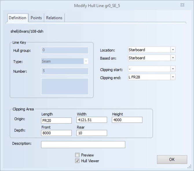
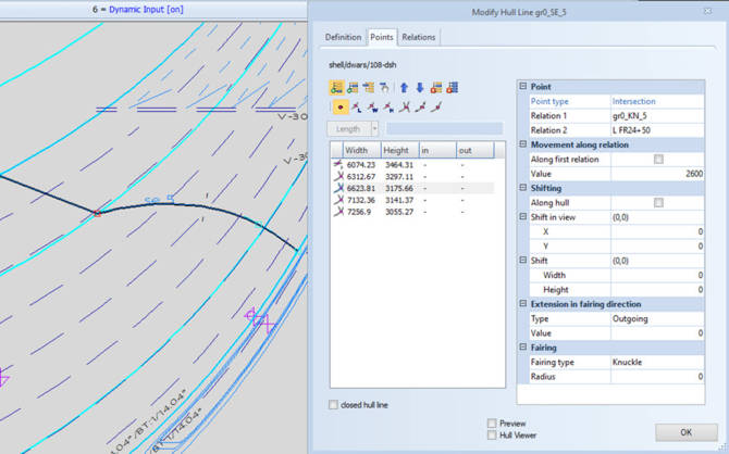
With the Hull Lines tool, the engineer can create and link any hull line to other elements, such as construction. These hull lines are created in a view and projected onto the shape. There is no limit to the number of lines and the shapes of the lines. Smart functions take care of knuckles, rounding, displacement of points or extensions in a given direction. Points can have a certain distance compared to each other with respect to other lines, regardless whether the shape is taken into account or not. Information from other lines can be used and points can be at a given ratio or angle. All adjustments are directly visible, so what you see is what you get.
Hull lines can also be entered asymmetrically. Each line can be given a specific purpose, like the border of a painted area or a reference for a shell frame. The so-called “in-plane” option ensures that a part of the hull line lies on a plane, which can also be used for shell frames. This has many advantages for production. The Hull Lines tool is an excellent example of how a particular specialization has been incorporated in the software functionality.
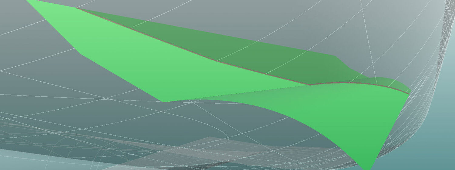
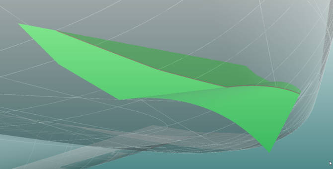
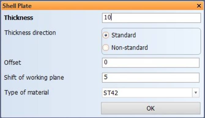
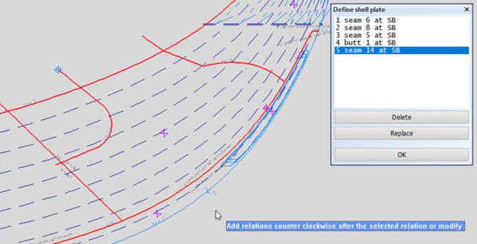
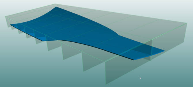
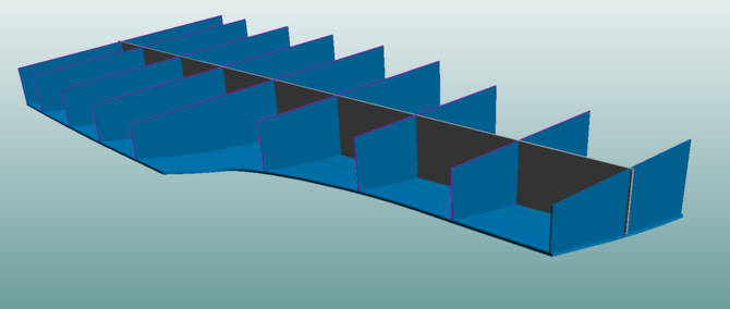
The tool for creating shell plates is very effective and accessible. It allows any engineer to create a shell plate by simply selecting the number of hull lines. The shell plate properties are clear: offset, thickness, direction and material, and all changeable. The user can apply the hull lines individually clockwise or counterclockwise. The contour is related to the hull lines, and therefore consistent. The result is directly visible in the view and in 3D. Weight, COG, size and other properties are calculated directly. The shell plates are visible in every section and the user can use them as a relation for the inner structure of the ship. This is especially handy when the shell plate has its offset inwards.
The shell plates can also be used for deck constructions with curved surfaces. Since the shape is determined by the surface and the hull lines, any shape is possible. During the above process, the engineer does not have to take production issues into account.
Multiple data sets are required to produce shell plates: expansion and shape data.
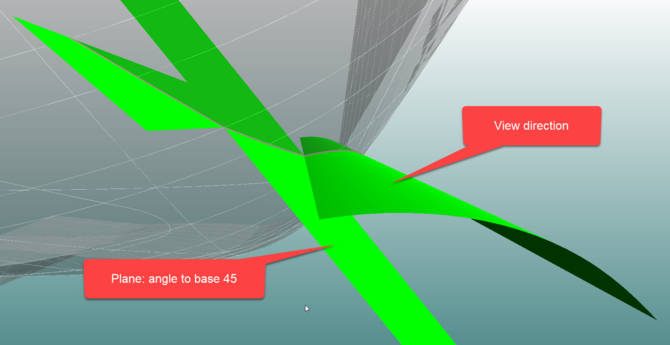
Template plane definition in all possible directions.
 Watch shell plate development webinar
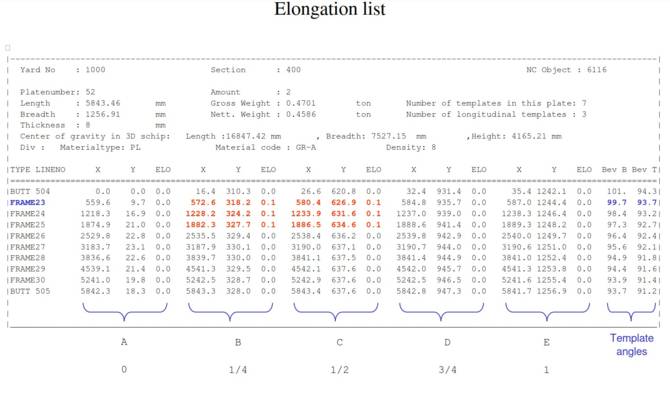
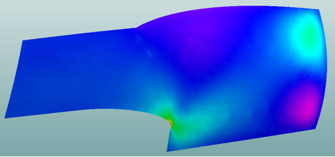
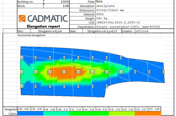
The deformation of a shell plate is still a manual process, which makes some knowledge of this specialization necessary. It is important that the specialist gets all the correct and necessary information to do the work properly: templates, elongation data and roller line. Because the new method determines elongation in all directions, the new deformation method from Nieland is supported. The colors of the stretches also provide a good indication of which areas should be stretched (See picture below). By stretching more on the green to yellow areas, and less on the light blue to green areas, the plate is already well deformed. The guidance provided and the suspension of the plate under the press is crucial in ensuring that the form is not guided negatively due to the suspension.

How then does one determine the processing time in advance, so that the correct relation between production time and plate size can be chosen? It is commonly known that the bigger plates are, the less welding is required. The system does not affect the knowledge of the experts in deforming. However, the system does give a number of parameters that allow making a fairly good estimation. The following are important parameters: the maximum elongation in both directions, minimum radius, maximum radius, plate type, dimensions, and material type in combination with the deforming time from the past. The parameters result in Big Data that generates a predictable estimation time of shell plates.
Production data for shell plates can be generated automatically. Various defaults and settings determine the style of the output. If one of the shell plates exceeds the engineer’s own estimation factors, based on the Big Data, action needs to be taken. In many cases, the shell plate must be narrowed, which still requires some expert knowledge. However, with the topology of the hull lines connected to the shell plates, this is quite a simple process and the new parameters can be used to compare the effect of the change.
In addition, the newest shell plate tools offer various functions that allow additional features like extra length, shrinkage compensation, bevel and weld information, reference lines and corner markers for assembly when using pin-jigs.
Conclusion
In the past, various specialists were required in shell plate development. Developments in CAD/CAM software have changed the way this process works, with much less dependence on individual experts. Decades of experience and highly specialized training is no longer required to produce accurate information for shell plate production. This allows engineers and designers to focus on creating new shapes for ships and sustainable designs, while the software takes care of calculations and the accuracy of data.
About the author: Paul Filius
Paul Filius has worked in the shipbuilding industry for more than 40 years. He started in the Netherlands as an apprentice. After three years of practical experience on the work floor of Tille Shipyards, he started his career in 1976 at the work preparation department at Centraalstaal.
Three years later, he moved to Numeric Centrum Groningen where he became involved in hull shape fairing. He has experienced the evolution of the shipbuilding industry: moving from hand-drawn designs to 2D and 3D designs, and learning programming to becoming the initiator of the first CADMATIC Hull software.
Currently, Paul works as a technical director in the CADMATIC Groningen office in the Netherlands. He focuses on gathering customer stories and use cases to prepare for software releases. He also defines long-term strategies for development and ensuring that the software is as flexible as possible and that it meets customer needs.
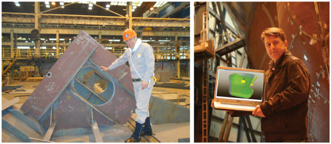
Over his more than 40 years in the shipbuilding industry, Paul Filius has seen the evolution of shell plate and related CAD development.