3D Model – Technology Island in Ship Design or a Central Piece for Shipbuilding Project Data?
This paper was presented for the first time at the annual Conference on Computer Applications and Information Technology in the Maritime Industries (COMPIT) held in Mülheim, Germany from 9-10 August 2021 where it won the COMPIT award.
Abstract
Historically, 3D models have been at the core of ship design solutions in shipbuilding. With the development of IT technology, the 3D model has taken on the position of a 3D dashboard and is more widely used. Adding information on top of the 3D model makes it an information-rich digital twin of the project, which can be used on any device, including AR/VR/XR. Besides the visual role, it can serve as a dashboard for communication, integration, consolidation, and an entry point for different interfaces at any stage of a shipyard’s activities. This paper presents several use cases of 3D dashboards based on CADMATIC eShare use by the shipyards and outlines the primary considerations for using digital twin platforms in shipbuilding.
1. Introduction
Shipbuilding has used 3D models for several decades. The contemporary design and building process relies heavily on 3D modeling as an engineering tool; it enables high-quality production data, facilitates project review, eases change management, and more. However, recent interest in digital twins, Cabos and Rostock (2018), and related expectations for digital shipbuilding raise questions about the use of 3D models. What is the potential value of using the same 3D model throughout the whole shipbuilding management process? How can the complexities of the same 3D model be managed for changing purposes throughout the ship’s life cycle?
In an ideal world, the 3D model is created incrementally, starting from the concept stage of the shipbuilding project. It is enhanced with details and used to extract production data; it may serve as a basis for marketing materials and rendered visualization, including AR/VR/XR and contain converted or raw 3D laser-scanned data. The same 3D model or a or filtered model can be used later for maintenance, repair, operation, training and retrofit purposes. It can become a digital twin that lives its digital life alongside the actual vessel.
The focus of shipbuilding design solutions on the 3D model might be too narrow: the 3D model is a “technology island” similar to an “automation island” in the production process. Many technological advancements focus on creating 3D models – from basic design to detailed design and production. Each stage of the shipbuilding process often focuses only on its own outcomes, such as hull design or piping and outfitting, and related outputs. Typically, only neighboring disciplines and project stages are covered, leaving gaps or ignoring the overall strategy and integration of the digital thread. For example, a model created for basic design and class approval is often not used for detailed design purposes. Plate nesting information is linked with planning and production but lacks alignment with outfitting disciplines. Material management needs to align EBOM and MBOM without verifying the latest changes in the design model. There are many other similar examples.
While each gap can be addressed individually, the overall PLM approach is still novel for shipbuilding. The expectation is that PLM can potentially resolve most of these inconsistencies. However, a typical PLM solution originates from mechanical CAD models with significantly fewer parts and less complexity. It only brings the automated approach of splitting the 3D model into parts and managing information about each piece independently. This approach considers a 3D model as a composition of many small 3D models for every item, and it can be enhanced by using 3D as a unifying interface to access data of each specific part. This article explores the typical uses of the 3D model in the shipbuilding cycle from the concept and contract stages to operation. It outlines specific use cases and explores the future possibilities of using 3D models in shipbuilding management.
2. 3D model and shipbuilding management activities
It is a relatively novel approach to use the 3D model throughout the entire shipbuilding process. It is a commonly used and accepted way of designing highly complex ships. The use of 2D drawings has become increasingly outdated, and the order of creation has turned to the extraction of 2D drawings from 3D models, and not 3D modeling according to 2D documentation. This was not the case some 15 years ago, when 2D drawings were the basis of ship design, approval, and production. In recent years, there have been significant shifts that were enabled by new computing technology and comprehensive access to 3D manipulation. It has provided numerous possibilities to avoid 2D documents. Examples of these include direct interfaces with CNC machines, welding robots and cobots, new options to submit 3D models for class approvals, and more.
All these uses of the 3D model are different. In some cases, the 3D model comes as an engineering model, and the visual representation only visualizes calculated data, such as in the case of 3D fairing or surface definition. In the case of 3D detailed design, it manages the arrangement complexities in crowded 3D spaces. It allows users to resolve conflicts in 3D arrangement, select the correct materials, and provides a common place for all disciplines to connect – align equipment with foundations, electrical cables with motor connections, etc.
Software providers embed an extremely high level of knowledge in modern CAD software and 3D modeling. CAD applications harness numerous automated functions, engineering practices, standards, and knowledge that have been accumulated over decades in the shipbuilding industry, Filius (2020). As a result, in the final stages of 3D modeling, a complete model is available that includes all disciplines, accurate geometrical information, topological and parametrical connections, a significant amount of meta-data, and links with 2D outputs for change management. At this stage, the focus of attention often shifts from design to production, assembly, and construction, and the 3D model remains an extra item or attachment to the project documentation package.

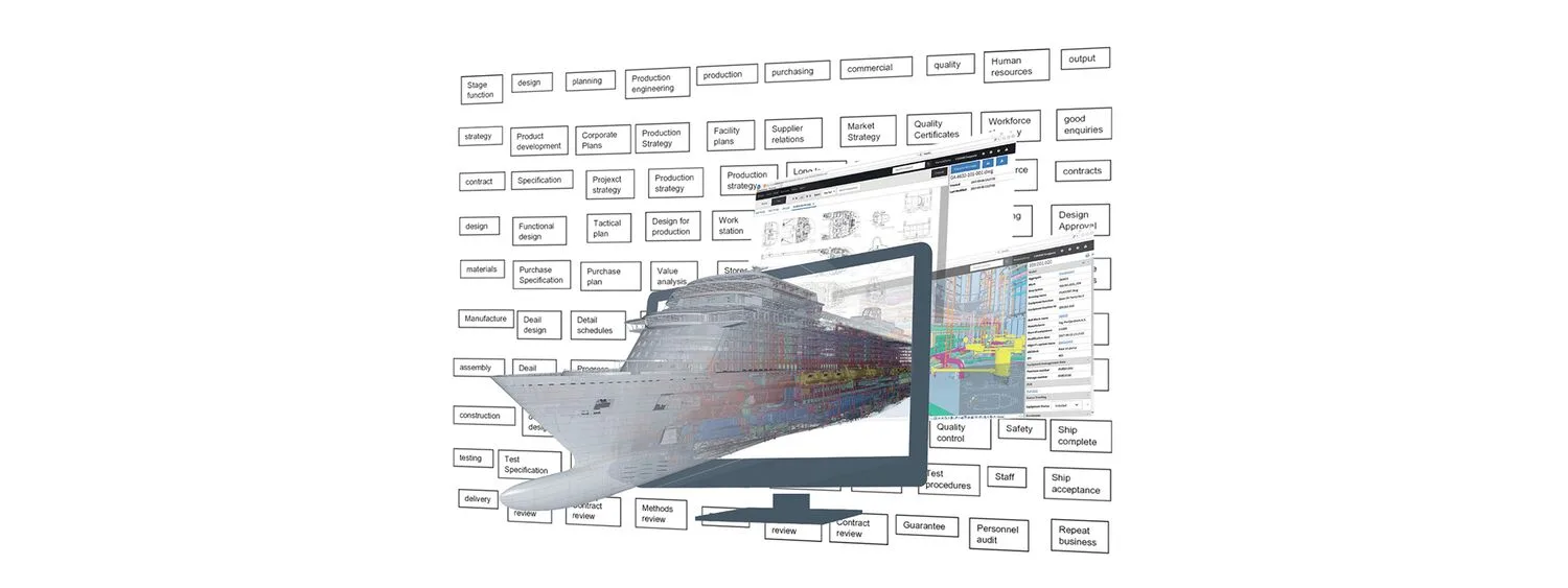
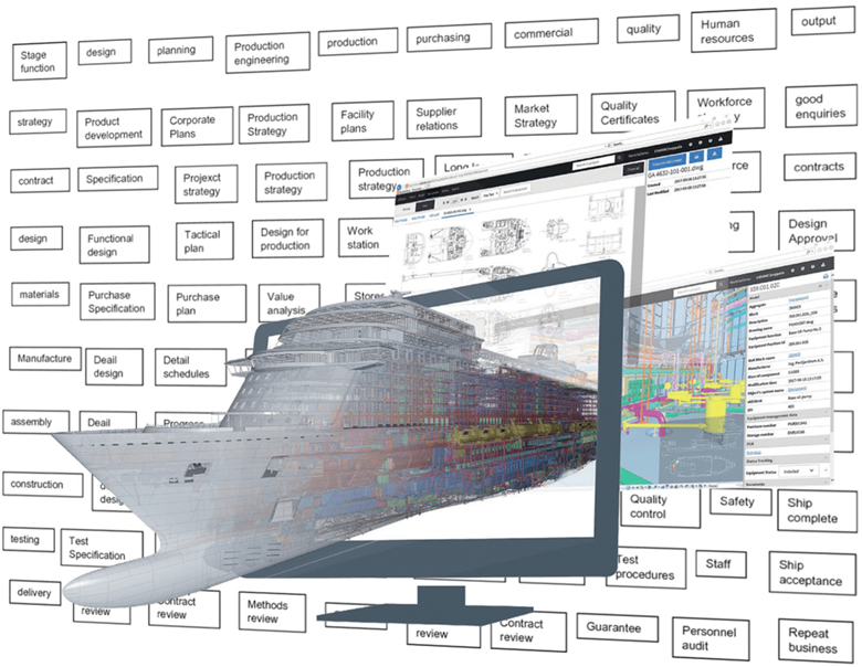
Fig.1 illustrates the typical use of the 3D model in CAD against the timeline of the overall shipbuilding management process. The period of 3D model use is somewhat restricted to design and partially includes construction. Typically, it is limited and fragmented. For example, it is possible to have several 3D models for different purposes or several models that were created in different design software packages. Specialized tools for calculations may have been used or several subcontractors responsible for only a limited part of the design may also have been involved. Interoperability between software solutions could facilitate the conversion and merging of 3D models into one entity, but it might become an obstacle if formats are not compatible. This issue has been tackled extensively in recent years with efforts to create standardized forms, such as IGES, JT, or STEP, and with project-based conversions as described by Sieranski and Zerbst (2019).
3. Example use cases of 3D models at shipyards
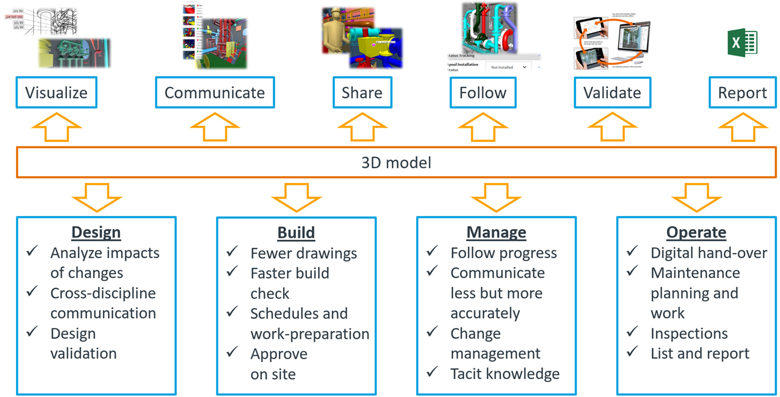
Several 3D model use case examples are presented in Fig.2, based on experience accumulated by CADMATIC in everyday interactions with shipyards and ship design offices. The examples illustrate the extended use of 3D models and do not include obvious scenarios, such as using the 3D model for collaboration design or production information purposes. The use cases are divided into three main clusters: Boost for communication, Integration of information flows, and Platform for Digital Twin.

3.1. Boost for communication
3.1.1 Communication within shipyards and shipyard networks
The use of 3D models facilitates communication within shipyards, and between the shipyard and subcontractors and shipyard groups. Instead of a paper- or email-based information flow, the engineering office and shipyard can use 3D model mark-ups and interfaces to VR/AR/XR applications. 3D models, which often include 3D laser-scanned data, are a more realistic representation of the ship than 2D documentation, project structures, or data tables.
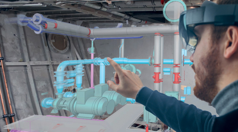
It was long accepted that the lack of IT technology prevented effective manipulation of 3D models due to heavy GPU requirements and the lack of VR developments, Agis et al. (2020). However, these constraints are in the past; current technologies enable 3D visualization on powerful workstations and tablets and XR devices, such as VR headsets or MS Hololens, with the possibility to manipulate 3D models in mixed reality and align 3D models with real objects. In recent years, much progress has been made in the use of 3D models in almost every ship design stage and beyond. A general conclusion is that the use of 3D models significantly enhances communication for all parties involved and serves as a more natural means of communication than old-fashioned 2D drawings and data sheets. Understanding a work breakdown structure based on a list of components or installation schedules is challenging. The same task is greatly eased when it can be visualized with colors inside the 3D model and interacted with in a live setting.
3.1.2 Project review and handover
Traditionally, shipbuilding CAD 3D models were locked inside ship design packages, required skills to navigate, and were otherwise available only for designers or for project review at most. However, with mature IT supporting a large amount of 3D data in recent years, it became possible to provide ship models for inspection on demand. In addition, it became possible to liberate 3D shipbuilding data and use significantly lighter and cheaper devices than specialized CAD desktops or virtual reality caves. 3D models in VR have been used for shipowner review, design validation, and production support.
The 3D model can remain as an extra item in the package that contains project information, including documentation, data from production and construction, and all related notes. These packages of information data about the same project will be different for the use of design collaboration, class approval, shipyard production workshops or shipowner. Alternatively, it can effectively serve as a natural entry point for information searches and to open linked data stored in other systems.
3.1.3 Visualization of installation instructions and replacement of paper drawings
Manufacturing and installation instructions can be visualized on mobile or wearable devices, thereby replacing paper drawings in the approval and production stage. Furthermore, direct data from the 3D model, such as geometrical representation, metadata, BOM, and workshop information is provided online to installation teams on site. At the same time, the outfitting part installation status can be added for progress following and as feedback to the design team.
Interaction with 3D data distinctively differentiates the digital era – the first attempts to standardize drawings aimed to improve readability and production quality. For the data-native generation, this poses unnatural limitations. Instead of a static snapshot, people prefer to obtain data on demand and then manipulate it. They also use the 3D model as an easy-to-understand interface, Seppälä (2019).
3.2. Integration of information flows
3.2.1 Integration with ERP, PLM/PDM, planning systems, and Manufacturing Execution System (MES)
For 3D evaluation, monitoring progress, and checking the parts and materials, shipyards can integrate the 3D model with PLM/PDM or ERP systems. Linked documents and system parts, including dimensional drawings and piping parts, provide a rich context when they are efficiently visualized as separate parts and as an integral part of the vessels’ 3D model. In addition, a 3D model linked to task planning at the detailed work breakdown level, kitting packages, and BOM visualizes planning, retrieval of tasks (welding, grinding, painting), and resource planning.
Integrating the 3D model with planning and manufacturing execution systems helps visualize the scheduling status of parts and blocks with color-coding, adding a visual aspect to work scheduling and progress monitoring. It also provides context for each work task by relating it to the overall production process and background data. Resource management systems are often focused on narrow tasks and reporting processes, leaving workshop staff without a direct link to the product they are producing and a significant amount of design and production-generated information, Seppälä and Brink (2020).
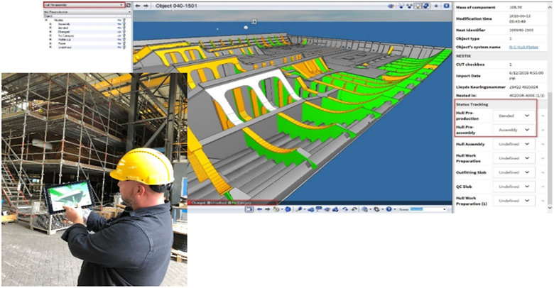
3.2.2 Integration with work packages and component tracking
Linking materials, fittings, and equipment with their digital counterparts in a 3D model provides additional benefits for integration. For work preparation and planning, the 3D model can be integrated with work planning systems and ERP for work package kitting visualization and shipyard resource management. Any item can be found in the digital model using RFID or QR codes as well as all related data from integrated systems – attributes, drawings, and instructions accessed on site. The shipyard can benefit from integrating 3D models with production systems, such as nesting and assembly controls. The hull production statuses for cutting, bending/pre-assembly, approval, and section assembly are visualized and monitored using a 3D model on a suitable device.
3.3. Platform for Digital Twin
Consolidating shipbuilding management information on a 3D dashboard and using the 3D model as a natural interface have considerable potential in shipbuilding. The discussion about the advantages and uses of the 3D model has, on the one hand, been an ongoing debate over the last decade, and on the other hand, – has provided a new perspective on continuity in the shipbuilding process and the blurring of borders between design stages and even disciplines.
Traditionally, ship design software has stored data that originated in the design stages and extended slightly towards the production stage. Decades ago, 3D browsers aimed to fill this gap, at least partially, by providing the possibility to review 3D models outside CAD. This approach was expanded recently with information management systems that serve as a platform for consolidating 3D data and for providing smart functionality to access data needed for different stages and purposes. The primary use cases of this access were presented in the previous sections.
However, one question needs special attention – how to store and access all the data that comprises the digital twin? If one considers this question purely from a PLM perspective, the answer will be as simple as storing any 3D models, such as the basic design model, detailed design model, production model with geometrical data for each object, etc., alongside other documentation drawings, schedules etc. A PDM system would provide a secure vault for 3D model storage, which would diminish the use of 3D data. Alternatively, using a shipbuilding-specific information management platform and supporting incremental creation of the 3D model and its use would boost digital shipbuilding.
Combining several 3D models and converting 3D models between different formats help to facilitate a one-model approach. It helps to consolidate 3D data in one platform and supports the approach based on a “universal” digital twin, in contrast with a specialized digital model for each use case.
Summary
The single source of truth is an attractive analogy and a trap at the same time. It provides the illusion of a central access point for all up-to-date data. The contemporary reality at shipyards is far from the ideal situation with a myriad of specialized systems, interfaces, and data storage methods used in different departments. A step that would provide unification is the expansion of the use of the 3D model, thereby ensuring support for specific needs of each discipline and shipbuilding process stage.
The use of 3D models would boost communication and integration without compromising shipbuilding’s specific purposes. Hopefully, in the future, 3D models will become a landscape instead of an island, and 3D technology will support the shipbuilding cycle as a whole, not as segmented stages.
References
AGIS, J.; BRETT, O.; EBRAHIMI, A.; KRAMEL, D. (2020), The Potential of Virtual Reality (VR) Tools and its Application in Conceptual Ship Design, 19th COMPIT Conf., Pontignano, pp.123-134
BRUCE, G. (2021) Shipbuilding Management, Springer Singapore
CABOS, C.; ROSTOCK, C. (2018), Digital Model or Digital Twin?, 17th COMPIT Conf., Pavone
SEPPÄLÄ, L. (2019), Drawingless Production in Digital Data-Driven Shipbuilding, 18th COMPIT Conf., Tullamore, pp.405-415
SEPPÄLÄ, L.; BRINK M. (2020), Link 3D data and integrated planning – Reduce shipyard workshop hours by at least 15%, Cadmatic https://cadmatic.com/en/resources/articles/link-3d-data-and-integrated-planning/
SIERANSKI, J.; ZERBST, C. (2019), Automatic Geometry and Metadata Conversion in Ship Design Process, 18th COMPIT Conf., Tullamore, pp.146-155